Lab-1:create vlan based Openflow flows in OVS

openflow_1

openflow_2

Precondition:

  • Mininet and OVS ver 2.0.2 on Virtual Box
  • vlan package installed on VM. Try below command to install vlan package
    • apt-get install vlan

Procedure:

  • Start mininet with single bridge, 2 hosts and no controller
mininet>sudo mn --controller=none --topo=single,3
  • Perform below steps on mininet to prep hosts to add vlan-id.


mininet>h1 vconfig add h1-eth0 100
mininet>h2 vconfig add h2-eth0 100
mininet>h1 route del –net 10.0.0.0 netmask 255.0.0.0
mininet>h2 route del –net 10.0.0.0 netmask 255.0.0.0
mininet>h1 ifconfig h1-eth0.100 10.0.0.1
mininet>h2 ifconfig h2-eth0.100 10.0.0.2
mininet>h1 ifconfig
mininet>h1 route

Case-1: Figure-1

mininet>sh ovs-ofctl add-flow s1 priority=100,in_port=1,dl_vlan=100,actions=output:2
mininet>sh ovs-ofctl add-flow s1 priority=100,in_port=2,dl_vlan=100,actions=output:1
mininet>h1 ping h2 //ping is successful

Start wireshark and capture frame, frames are encapsulated into vlan-id=100

Case-2: Modify VLAN-ID (Figure-2)

  • Delete h2 vlan interface (h2-eth0.100) and add vlan interface 200


mininet>h2 vconfig rem h2-eth0.100
mininet>h2 vconfig add h2-eth0 200
mininet>h2 ifconfig h2-eth0.200 10.0.0.2
  • Add flow to modify vlan-id


mininet>sh ovs-ofctl add-flow s1 priority=100,in_port=1,dl_vlan=100,actions=mod_vlan_vid:200,output:2
mininet>sh ovs-ofctl add-flow s1 priority=100,in_port=2,dl_vlan=200,actions=mod_vlan_vid:100,output:1
mininet>h1 ping h2 //ping is successful

Case-3: Strip VLAN-ID (Figure-3)

  • Delete h2 vlan interface (h2-eth0.200).


mininet>h2 vconfig delete h2-eth0.200
mininet>h2 ifconfig h2-eth0 down
mininet>h2 ifconfig h2-eth0 up
  • Add flow to modify & strip vlan-id


mininet>sh ovs-ofctl add-flow s1 priority=100,in_port=1,dl_vlan=100,actions=strip_vlan,output:2
mininet>sh ovs-ofctl add-flow s1 priority=100,in_port=2,actions=mod_vlan_vid:100,output:1

Certified Kubernetes Administrator (CKA) Exam notes – Default Service Account in the pod

Every Kubernetes namespace contains at least one ServiceAccount: the default ServiceAccount for that namespace, named default. If you do not specify a ServiceAccount when you create a Pod, Kubernetes automatically assigns the ServiceAccount named default in that namespace.

Let’s examine the default service account

Create a pod name nginx and run the command ‘kubectl get pods nginx -o yaml | grep -i serviceAccontName’. A service account named ‘default’ will be displayed

Kubernetes mounts a default service account to each pod if the pod doesn’t specify any service account in the manifest. Below is the mount path in the pod

But can pod access Kubernetes API using the default service account. Let’s examine it. Login to the pod and run the below commands

#Login to the pod

Kubectl exec -it nginx /bin/sh

# Point to the internal API server hostname
APISERVER=https://kubernetes.default.svc

# Path to ServiceAccount token
SERVICEACCOUNT=/var/run/secrets/kubernetes.io/serviceaccount

# Read this Pod's namespace
NAMESPACE=$(cat ${SERVICEACCOUNT}/namespace)

# Read the ServiceAccount bearer token
TOKEN=$(cat ${SERVICEACCOUNT}/token)

# Reference the internal certificate authority (CA)
CACERT=${SERVICEACCOUNT}/ca.crt

# Explore the API with TOKEN
curl --cacert ${CACERT} --header "Authorization: Bearer ${TOKEN}" -X GET ${APISERVER}/api

The output will be something like this

All good we can reach the API server using the service account

Let’s see if we can actually do something in the API server. Run the curl to list the pods in the default namespace.

curl –cacert ${CACERT} –header “Authorization: Bearer ${TOKEN}” -X GET ${APISERVER}/api/v1/namespaces/default/pods

Looks like the default service account doesn’t have any role defined. It is not allowed to list pods.

Let’s assign a role to the default service account to list pods and then try the same command again.

Create role and role binding. Note: –serviceaccount format in rolebinding is <namespace>:<service account name>

Create a role: controlplane $ kubectl create role default-sa-role –verb=list –resource=pod

Create role binding: kubectl create rolebinding default-sa-rolebinding –role=default-sa-role –serviceaccount=default:default

Now that we have assigned a role to the default service account it can list the pods. Let’s try the above curl command again.

Note: We don’t need to use the default service account. We can define our own service account in the

References:

https://kubernetes.io/docs/tasks/run-application/access-api-from-pod/

Lab-55: Universal Plug And Play (UPnP) protocol

In this lab we will learn about about Universal Plug And Play (UPnP) protocol. UPnP protocol is used in many household devices, the purpose of this protocol is to discover devices, their capabilities and interact with devices. UPnP operates over UDP protocol using HTTP also known as HTTPU.  UPnP protocol standard can be found here

UPnP technology defines an architecture for pervasive peer-to-peer network connectivity of intelligent appliances, wireless devices, and PCs of all form factors. It is designed to bring easy-to-use, flexible, standards-based connectivity to ad-hoc or unmanaged networks whether in the home, in a small business, public spaces, or attached to the Internet. UPnP technology provides a distributed, open networking architecture that leverages TCP/IP and Web technologies to enable seamless proximity networking in addition to control and data transfer among networked devices

UPnP protocol uses Simple Service Discovery Protocol (SSDP) for device discovery. SSDP is a text-based protocol based on HTTPU (HTTP over UDP). It uses UDP as the underlying transport protocol. Services are announced by devices with multicast addressing
to a specifically designated IP multicast address at UDP port number 1900. In IPv4, the multicast address is 239.255.255.250.

UPnP protocol terminology:

action:
Command exposed by a service. Takes one or more input or output arguments. 
May have a return value

control point: 
Retrieves device and service descriptions, sends actions to services, 
polls for service state variables, and receives events from services

device description: 
Formal definition of a logical device, expressed in the UPnP Template 
Language. Written in XML syntax. Specified by a UPnP vendor by filling in 
the placeholders in a UPnP Device Template, including, e.g., manufacturer 
name, model name, model number, serial number, and URLs for control, 
eventing, and presentation

service description:
Formal definition of a logical service, expressed in the UPnP Template 
language. Written in XML syntax. Specified by a UPnP vendor by filling in 
any placeholders in a UPnP Service Templat

service type:
Standard service types are denoted by urn:schemas-upnp-org:service: followed
 by a unique name assigned by a UPnP forum working committee, colon, and an 
integer version number

SOAP Simple Object Access Protocol: 
A remote-procedure call mechanism based on XML that sends commands and 
receives values over HTTP

SSDP Simple Service Discovery Protocol:
A multicast discovery and search mechanism that uses a multicast variant of 
HTTP over UDP

Protocol is broken down in three steps 1) Discovery 2) Description and 3) Control. Let’s go over each steps and see what function they perform

Step-1: Discovery

Discovery is the step 1 in UPnP networking. When a device is added to the network, the UPnP discovery protocol allows that device to advertise its services to control points on the network. Similarly, when a control point is added to the network, the UPnP discovery protocol allows that control point to search for devices of interest on the network. UPnP uses Simple Service Discovery Protocol (SSDP) for discovery.

Below picture taken from standard show discovery architecture. On the right hand side we have devices and left hand side machine interested in devices and fetching info from devices, it can be another device or PC

Note: A physical can have multiple virtual devices and services

upnp_1

Devices advertises its services using NOTIFY discovery message. Client search for services using M-SEARCH message. Basically there are three message types related to discovery and they start with these lines:

NOTIFY * HTTP/1.1\r\n 
M-SEARCH * HTTP/1.1\r\n 
HTTP/1.1 200 OK\r\n

Advertisement with NOTIFY

When a device is added to the network, it shall send a multicast message with method NOTIFY and ssdp:alive in the NTS header field in the following format. Values in italics are placeholders for actual values

Each message contains information specific to the embedded device (or service) as well as information about its enclosing device. Messages shall include duration until the advertisements expire (max-age); if the device remains available, the advertisements shall be re-sent (with new duration). If the device becomes unavailable, the device should explicitly cancel its advertisements, but if the device is unable to do this, the advertisements will expire on their own

upnp_4

Search request with M-SEARCH

When a control point desires to search the network for devices, it shall send a multicast request with method M-SEARCH in the following format. Control points that know the address of a specific device are allowed to also use a similar format to send unicast requests with method M-SEARCH. For multicast M-SEARCH, the message format is defined below. Values in italics are placeholders for actual values.

upnp_2

Note: No body is present in requests with method M-SEARCH, but note that the message shall have a blank line following the last header field. Note: The TTL for the IP packet should default to 2 and should be configurable.

Search response

To be found by a network search, a device shall send a unicast UDP response to the source IP address and port that sent the request to the multicast address. Any device responding to a unicast M-SEARCH should respond within 1 second.

The URL specified in the LOCATION header field of the M-SEARCH response shall be reachable by the control point to which the response is directed

The response shall be sent in the following format. Values in italics are placeholders for actual values.

upnp_3

Devices responding to a multicast M-SEARCH should wait a random period of time between 0 seconds and the number of seconds specified in the MX field value of the search request before responding, in order to avoid flooding the requesting control point with search responses from multiple devices

Device unavailable — NOTIFY 

When a device and its services are going to be removed from the network, the device should multicast an ssdp:byebye message

upnp_18

Note: No body is present for messages with method NOTIFY, but note that the message shall have a blank line following the last header field. The TTL for the IP packet should default to 2 and should be configurable.

Step-2: Description

After a control point has discovered a device, the control point still knows very little about the device — only the information that was in the discovery message, i.e., the device’s (or service’s) UPnP type, the device’s universally-unique identifier, and a URL to the device’s UPnP description. For the control point to learn more about the device and its capabilities, or to interact with the device, the control point shall retrieve a description of the device and its capabilities from the URL provided by the device in the discovery message

The UPnP description for a device is partitioned into two logical parts: a device description describing the physical and logical containers, and service descriptions describing the capabilities exposed by the device.  A UPnP device description is written by a UPnP vendor. The description is in XML syntax and is usually based on a standard UPnP Device Template.

A UPnP service description includes a list of commands, or actions, to which the service responds, and parameters, or arguments for each action. A service description also includes a list of variables. These variables model the state of the service at run time, and are described in terms of their data type, range, and event characteristics

upnp_16

upnp_15

This is how my device description looks like:

upnp_17

This is how service description looks like in my device:

upnp_19

Step-3: Control

Given knowledge of a device and its services, a control point can ask those services to invoke actions and receive responses indicating the result of the action. Invoking actions is a kind of remote procedure call; a control point sends the action to the device’s service, and when the action has completed (or failed), the service returns any results or errors.

upnp_5

To control a device, a control point invokes an action on the device’s service. To do this, a control point sends a suitable control message to the fully qualified control URL for the service obtained from the controlURL sub element of the service element of the device description

Below is a listing of a control message sent using the POST method followed by an explanation of the header fields and body. To invoke an action on a device’s service, a control point shall send a request with method POST in the following format. Values in italics are placeholders for actual values

upnp_6

UPnP profiles SOAP 1.1, NOT REQUIRING that all devices support all allowed features of SOAP 1.1, but devices and control points shall support all mandatory features of SOAP 1.1

Demo

Demo is divided in 3 steps 1) Discovery 2) Description and 3) Control.

Step-1: Discovery

You can do discovery manually or using Python script.

Manual Discovery

For manual discovery launch Wireshark and filter for protocol SSDP. In my case I saw SSDP response message came from my set top box at address 192.168.0.1.  On inspecting the the message you will find the attribute LOCATION: http://192.168.0.1/rootDesc.xml, note it down we will need it in next step. This is where root device service description is listed

upnp_7

Automatic Discovery using Python script

Copy & paste below Python code in the file UPnP_Discovery.py. This script will send M-SEARCH message and print the response received from the device

import socket

msg = \
 'M-SEARCH * HTTP/1.1\r\n' \
 'HOST:239.255.255.250:1900\r\n' \
 'ST:upnp:rootdevice\r\n' \
 'MX:2\r\n' \
 'MAN:"ssdp:discover"\r\n' \
 '\r\n'

# Set up UDP socket
s = socket.socket(socket.AF_INET, socket.SOCK_DGRAM, socket.IPPROTO_UDP)
s.settimeout(10)
s.sendto(msg, ('239.255.255.250', 1900) )

try:
 while True:
 data, addr = s.recvfrom(65507)
 print addr, data
except socket.timeout:
 pass

Execute the script, you will find LOCATION: http://192.168.0.1/rootDesc.xml in response, note it down we will need it in next step

c:\Python27>python UPnP_Discovery.py
('192.168.0.1', 1900) HTTP/1.1 200 OK
CACHE-CONTROL: max-age=3600
ST: upnp:rootdevice
USN: uuid:52d57227-22ac-4f46-9a50-1a63ff84b88a::upnp:rootdevice
EXT:
SERVER: Linux/2.6.18_pro500 UPnP/1.0 MiniUPnPd/1.5
LOCATION: http://192.168.0.1:5000/rootDesc.xml
OPT: "http://schemas.upnp.org/upnp/1/0/";
01-NLS: 1
BOOTID.UPNP.ORG: 1
CONFIGID.UPNP.ORG: 1337

Step-2: Description

On web browser type in the LOCATION from step-1, http://192.168.0.1/rootDesc.xml. This web page provides device and service description, in my case it is my set top box from company called ARRIS.

We are interested in couple of things in this web page 1) Servicetype 2) ControlURL and 3) SCPDURL. SCPDURL (or Service Description URL) provide service commands (or action) and arguments for the command. ControlURL provides the url needed to invoke commands

In my case these are the settings for above three attributes:

Service type: WANCommonInterfaceConfig
controlURL: /ctl/CmnIfCfg
SCPDURL: /WANCfg.xml

upnp_9

In browser type in the <base url> + <SCPDURL>, http://192.168.0.1:5000/WANCfg.xml. Here we will find SOAP Actions, I am interested in SOAP Action GetCommonLinkProperties which has four output arguments. This action provide link status of my set top box

As you can see action GetCommonLinkProperties provides four output arguments

Note: Output arguments are specified as <direction>out</direction> and input arguments are specified as <direction>in</direction>

upnp_10

As you can see each argument is tied to <relatedStateVariable> which tell us what kind of output format we can expect

upnp_11

Now we know what SOAP Action (or command) to execute and the arguments it takes. In my case it is a read action so I will not provide any argument with SOAP  request. Next step is to execute SOAP request

Step-3: Control

In Control step we will execute SOAP request with the action. We have two options to execute SOAP request 1) Manually using POSTMAN or 2) using Python script

Manual execution of SOAP request using POSTMAN

It is going to be a POST request so select request type POST. If you are not familiar with POSTMAN refer to Lab-44

POSTMAN url: <base url> + <controlUrl>. http://192.168.0.1:5000/ctl/CmnIfCfg

Copy and paste below SOAP envelope in POSTMAN body.  Specify SOAP Action: GetCommonLinkProperties and Service type: WANCommonInterfaceConfig

Note: Replace bold italics text with your setting

<s:Envelope    
 xmlns:s="http://schemas.xmlsoap.org/soap/envelope/"    
 s:encodingStyle="http://schemas.xmlsoap.org/soap/encoding/">     
 <s:Body>        
 <u:GetCommonLinkProperties xmlns:u="urn:schemas-upnp-org:service:WANCommonInterfaceConfig:1">        
 </u:GetCommonLinkProperties>  
 </s:Body>  
</s:Envelope>

upnp_12

Create header with SOAP Action and Service type

Note: Replace bold italics text with your setting

Content-type: text/xml
SOAPACTION: urn:schemas-upnp-org:service:WANCommonInterfaceConfig:1#GetCommonLinkProperties

upnp_13

Click on Send button, set top box respond back with link status.

upnp_14

Automatic execution of SOAP Action using Python script

Copy and paste below Python code in file UPnP_SOAP_Request.py. I used the code from this blog

Note: Replace bold italics text with your setting

import sys
import httplib, urllib
import re
 
action = sys.argv[1]
 
conn = httplib.HTTPConnection("192.168.0.1:5000")
soap_data = '<s:Envelope xmlns: s="http://schemas.xmlsoap.org/soap/envelope" s:encodingStyle="http://schemas.xmlsoap.org/soap/encoding"><s:Body><u:'+action+' xmlns:u="urn:schemas-upnp-org:service:WANCommonInterfaceConfig:1"></u:'+action+'></s:Body></s:Envelope>'
 
params = urllib.urlencode({'q': 'set'})
headers = { "Content-Type": "text/xml", "Content-Length": "%d" % len(soap_data), "SOAPACTION": "urn:schemas-upnp-org:service:WANCommonInterfaceConfig:1#"+action+'"' }
 
conn.request("POST", "/ctl/CmnIfCfg", "", headers)
conn.send(soap_data)
 
response = conn.getresponse()
 
#FOR DEBUG
print response.status, response.reason
print response.read()

Execute the script with  argument like this with action as argument:

c:\Python27>python UPnP_SOAP_Request.py GetCommonLinkProperties

You will see the Link status output similar to what we saw in POSTMAN

200 OK
<?xml version="1.0"?>
<s:Envelope xmlns:s="http://schemas.xmlsoap.org/soap/envelope/" s:encodingStyle="http://schemas.xmlsoap.org/soap/encoding/">
<s:Body><u:GetCommonLinkPropertiesResponse xmlns:u="urn:schemas-upnp-org:service:WANCommonInterfaceConfig:1">
<NewWANAccessType>Cable</NewWANAccessType>
<NewLayer1UpstreamMaxBitRate>1000000</NewLayer1UpstreamMaxBitRate>
<NewLayer1DownstreamMaxBitRate>10000000</NewLayer1DownstreamMaxBitRate>
<NewPhysicalLinkStatus>Up</NewPhysicalLinkStatus>
</u:GetCommonLinkPropertiesResponse>
</s:Body>
</s:Envelope>


Lab-54: MQTT over WebSocket

In the Lab-46 we learned about MQTT protocol. In this lab we will learn how to use MQTT over WebSocket. So why do we need  MQTT over WebSocket ?. It is to support MQTT on browser

WebSocket

WebSocket is web transport protocol. It is an upgrade from HTTP protocol. HTTP protocol is still in use but replaced by WebSocket in many applications. HTTP worked best for request and response type communication, where a browser request for data and server respond with data. A unidirectional communication. A polling mechanism was introduced in HTTP where client (browser) continuously poll server for data. Like client asking server if it has something to send. which was not very efficient. WebSocket solves this problem by creating bi-directional connection between client and server. Now client and server can send data asynchronously. This is very useful for web applications like Chat where client and sender can send/receive data

In order to support MQTT broker and client on web browser we need to run it over WebSocket. So in this lab instead of running MQTT client on Linux machine we will be running  it on web browser. Similarly we will be using web based MQTT broker

Pre-requisite:

  1. Windows 10 laptop
  2. Paho-mqtt javascript library

Procedure:

Step-1. Download Paho-mqtt javascript library

  1. Go to this link and download zip file to you pc
  2. Unzip the file. There will be  mqtt-ws31.js file under ‘paho.mqtt.javascript-master\src’

Step-2. Open a notepad and paste below code. Save it as index.html file. This code simulates MQTT client over WebSocket. It will create connection to MQTT broker and publish a message

In this lab we will be using MQTT cloud broker at ‘broker.mqttdashboard.com’

invoke paho-mqtt client library. Give the full path where mqtt-ws31.js file is located


Below code creates connection to broker ‘broker.mqttdashboard.com’ on port 8000 and provide a client-id

// Create a client instance
 client = new Paho.MQTT.Client("broker.mqttdashboard.com", 8000, "clientId");

Add your topic name here

message.destinationName = "divinelife/topic/1";

Below complete code

<!DOCTYPE html>
<html>
<head>
    <meta charset="utf-8" />
    <title>MQTT over Websocket</title>
</head>
<body>
    
Message published to Cloud MQTT broker
             // Create a client instance     client = new Paho.MQTT.Client("broker.mqttdashboard.com", 8000, "clientId");                // set callback handlers     client.onConnectionLost = onConnectionLost;    // connect the client     client.connect({ onSuccess: onConnect });    // called when the client connects    function onConnect() {             // Once a connection has been made, make a subscription and send a message.             console.log("onConnect");             var msg = "Hello Cloud MQTT from DivineLife"             message = new Paho.MQTT.Message(msg);             message.destinationName = "divinelife/topic/1";             client.send(message);         } // called when the client loses its connection         function onConnectionLost(responseObject) {             if (responseObject.errorCode !== 0) {                 console.log("onConnectionLost:" + responseObject.errorMessage);             }         } </body> </html>


Step-3. Go to this link to access web based broker

Click on Connect. leave other fields as it is

mqtt-ws-1

Click on ‘Add New Topic Subscription’ under Subscriptions to subscribe to a topic. Enter topic name , this is the same topic we will be publishing using javascript program.  click on ‘Subscribe’.

mqtt-ws_2

Step-4. Execute javascript program we created in step-2. I am running it in Google Chrome. Open a new tab and type ‘file:///C:/’ , navigate to your  program ‘index.html’ and click on it. It will execute program and send message to broker.

Note: If you need to see console debug messages or debug script, press F12 on Chrome browser and click on Console tab

mqtt-ws_5

Check message in broker, you should see below message under Messages

mqtt-ws_6


Let’s see what’s happening under the hood

First browser asked server to upgrade to WebSocket and use mqtt as sub-protocol (Sec-WebSocket-Protocol). This is a way of telling the server to use WebSocket protocol instead of HTTP

mqtt-ws_4

Server respond back and agree to upgrade to WebSocket protocol and sub-protocol as mqtt

mqtt-ws_4

After initial handshake, browser sends MQTT packet encapsulated in WebSocket.

CONNECT message from client

mqtt-ws_10

CONNACK from broker

mqtt-ws_11

PUBLISH from client

mqtt-ws_12


Lab-53: AMQP 1.0 protocol

1.0 Introduction

In the series of IoT protocol, in this lab we will go over AMQP protocol theory and then demo using RabbitMQ an open source AMQP broker and Qpid Proton as AMQP client. AMQP stands for Advanced Messaging Queue Protocol. AMQP 1.0 is the primary protocol used in Azure IoT hub.

AMQP 1.0 and pre AMQP 1.0 are totally different protocols. AMQP 1.0 is a standard protocols while pre-AMQP 1.0 are drafts. You can download AMQP 1.0 standard from here. You can read the difference between AMQP 1.0 and pre-AMQP 1.0 here

AMQP is a publish and subscribe protocol. In a typical pub sub protocol you have a producer, a broker and a consumer. The job of producer is to generate message. Broker store the messages in a queue until consumer comes and read the messages. Pub sub protocol decouple producer from consumer, what this mean is producer doesn’t know about consumer and consumer doesn’t know about producer. Consumer can be offline while producer generates message and whenever it comes online it read messages.

AMQP is a wire protocol which means it provides rules for data encoding on the wire. Let’s start from bottom up that’s how AMQP standard organized. I will start with how data is encoded, then the concept of container/node and various endpoints and  finally message transfer

2.0 AMQP Types

AMQP defines type system for encoding data. AMQP supports 4 types. In this tutorial we will go over Primitive and Described types

  1. Primitive types
  2. Described types
  3. Compound types
  4. Restricted types

Primitive types

AMQP defines Primitive types for encoding common scalar values and common collections.

  • The scalar types include booleans, integral numbers, floating point numbers, timestamps, UUIDs, characters, strings, binary data, and symbols.
  • The collection types include arrays and lists

An AMQP encoded data stream consists of untyped bytes with embedded constructors. The embedded constructor indicates how to interpret the untyped bytes that follow.

Let’s see how variable string and fixed data encoded using Primitive types

Variable width encoding:

The size of variable-width data is determined based on an encoded size that prefixes the data. The width of the encoded size is determined by the subcategory of the format code for the variable width value

Below example show how to encode a string “Hello Glorious Messaging World” using Primitive type. The first byte is a constructor 0xA1, which represents variable width data with one octet for data length (the size of length field is one octet). Next to constructor byte is length of data in this case 0x1E

amqp_1

Below is the breakdown of Constructor with 4 bits of subcategory and 4 bits of subtype.

amqp_2

Subcategory is defined in this table. There is fixed width subcategory to encode numbers and variable width to encode strings

amqp_4

Let’s see how it looks on wire. Below show Wireshark capture of variable width encoded string “Hello Glorious Messaging World”. As you can see encoded string starts with constructor 0xa1 then length filed of one octet 0x1e and then string

amqp_3

Fixed width encoding:

The size of fixed-width data is determined based solely on the subcategory of the format code for the fixed width value.

Below is an example fixed width encoding. In case of fixed width encoding there is no length octet after constructor. The length can be computed from subcategory. It is encoded using fixed width subcategory 0x54 (smallint) which mean one octet of data

amqp_5

Described types

AMQP provides a means to annotate Primitive types with descriptor to create described types. Described types is a way to create custom types

– A descriptor defines how to produce a domain specific type from an AMQP primitive value

amqp_6


amqp_7


3.0 AMQP Frame Transfer

AMQP network consists of nodes connected via links. Nodes are named entities responsible for the safe storage and/or delivery of messages. Messages can originate from, terminate at, or be relayed by nodes. A link is a unidirectional route between two nodes. A link attaches to a node at a terminus. There are two kinds of terminus: sources and targets. A terminus is responsible for tracking the state of a particular stream of incoming or outgoing messages. Sources track outgoing messages and targets track incoming messages. Messages only travel along a link if they meet the entry criteria at the source. As a message travels through an AMQP network, the responsibility for safe storage and delivery of the message is transferred between the nodes it encounters.

Container: is an application, a client app or a broker

Node: is a message producer or consumer. Within an application you can have process which produces messages and process which consume messages

Connection: is a tcp connection between two containers

Channel: A connection is divided into multiple unidirectional channels

Session: Is a logical binding of channels between two nodes. Two unidirectional channels form a bi-directional session. A connection can have multiple sessions

Link: are unidirectional  between two sessions. A session can have multiple links. Within a session Links are uniquely identified by link handle. Links contains target of message delivery

amqp_8

Details on above entities

Connection:

A Connection may contain multiple independent Sessions, up to the negotiated channel numbers

Connection opening:

A connection opened between two containers by sending Open frame. First a TCP connection is established and header frame exchanged to negotiate AMQP version. After that each peer send Open frame to setup connection

  • After establishing or accepting a TCP connection and sending the protocol header, each peer MUST send an open frame before sending any other frames. The open frame describes the capabilities and limits of that peer. The open frame can only be sent on channel 0.
  • After sending the open frame and reading its partner’s open frame a peer MUST operate within mutually acceptable limitations from this point forward

amqp_16

Connection idle timeout

Connections are subject to idle timeout threshold. Timeout is triggered by local peer if no AMQP frames are received after threshold exceeded.The idle timeout is measured in milliseconds, and starts from the time the last frame is received. If the threshold is exceeded, then a peer SHOULD try to gracefully close the connection using a close frame with an error explaining why. If the remote peer does not respond gracefully within a threshold to this, then the peer MAY close the TCP socket

At connection open each peer communicates the maximum period between activity (frames) on the connection that it desires from its partner

amqp_22

Session:

An AMQP  session binds together two unidirectional channels to form a bidirectional, sequential conversation between two containers. Session is created using Begin performative and deleted using End performative

Establishing a session:

  • A Session is established by creating a session endpoint and assigning it an un-used channel number. Sending begin and announcing association of session endpoint with outgoing channel number
  • Upon receiving the begin the partner will check the remote-channel field and find it empty. This indicates that the begin is referring to remotely initiated session
  • The partner will therefore allocate an unused outgoing channel for the remotely initiated session and indicate this by sending its own begin setting the remote-channel field to the incoming channel of the remotely initiated session

amqp_17

Link:

Within a Session a Link is a unidirectional route between a source and a target node, one at each end of the Connection. Links are the paths over which messages are transferred.

Links are unidirectional. Pairs of links are bound to create full duplex communication channels between endpoints. A single Session may be associated with any number of Links.

Links provide a credit-based flow control scheme based on the number of messages transmitted, allowing applications to control which nodes to receive messages from at a given point (e.g., to explicitly fetch a message from a given queue).

Link contains source and target names these are the names of queues or topics in the partner

Links are created using performative attached and destroyed using detach

A link attaches to a node at a terminus. There are two kinds of terminus: sources and targets. A terminus is responsible for tracking the state of a particular stream of incoming or outgoing messages

4.0 AMQP Frame

Frames are divided into three distinct areas: a fixed width frame header, a variable width extended header, and a variable width frame body

frame header

The frame header is a fixed size (8 byte) structure that precedes each frame. The frame header includes mandatory information necessary to parse the rest of the frame including size and type information.

extended header

The extended header is a variable width area preceding the frame body. This is an extension point defined for future expansion. The treatment of this area depends on the frame type.

frame body

The frame body is a variable width sequence of bytes the format of which depends on the frame type.

amqp_18

amqp_19

5.0 Performative

amqp_15


6.0 QOS

AMQP provides QOS using disposition and transfer performative. Three QOS types are supported which is very similar to MQTT

  1. At-most once

If the sending application settles the delivery before sending it, this results in an at-most-once guarantee. The sender has indicated up front with his initial transmission that he has forgotten everything about this delivery and will therefore make no further attempts to send it. This is fire and forget approach.

If this delivery makes it to the receiver, the receiver clearly has no obligation to respond with updates of the receiver’s delivery state, as they would be meaningless and ignored by the sender

If message lost it will not be delivered again. It is a best effort service

amqp_12

2. At-least once

Sender sends delivery with settled = false and only settle when settled = true disposition received from the receiver. Sender sends transfer message and keeps it’s delivery tag in unsettled map

Receiver settle immediately upon processing the message. Receiver sends disposition with settled = true

Sender receives disposition with settled = true and removes delivery tag from unsettled map. At this point the delivery is considered settled and forgotten.

If transfer message is lost, sender will send the message again after ttl expiry

If the disposition frame is lost, sender will send the message again after ttl expiry

Receiver can get duplicate message. It is a two step process

amqp_13

3. Exactly once

In this method receiver receives message only once, duplicate message at receiver is not allowed, AMQP achieve this by having acknowledge from both Sender and Receiver. Sender sends transfer message with settled = false and keeps delivery tag in unsettled map

Receiver sends disposition with settled = false

sender sends disposition back with settled=true and remove delivery tag from unsettled map.

Upon receiving the settled = true from sender receiver also settled and removed tag from unsettled map

If transfer message is lost, sender will send the message again after ttl expiry

If the disposition frame from receiver  is lost, it will send is again after ttl expiry. If receiver doesn’t receive settled = true for delivery it will send disposition with settled = false again

Receiver will get only one message.

amqp_14


7.0 Message Transfer

Messaging frame follow AMQP transfer frame.

An annotated message consists of the bare message plus sections for annotation at the head and tail of the bare message. There are two classes of annotations: annotations that travel with the message indefinitely, and annotations that are consumed by the next node

The bare message consists of three sections: standard properties, application-properties, and application-data (the body). Application-properties is where you can add your properties

The bare message is immutable within the AMQP network. That is, none of the sections can be changed by any node acting as an AMQP intermediary

amqp_20

Altogether a message consists of the following sections:

  • Zero or one header.
  • Zero or one delivery-annotations.
  • Zero or one message-annotations.
  • Zero or one properties.
  • Zero or one application-properties.
  • The body consists of one of the following three choices: one or more data sections, one or more amqp-sequence sections, or a single amqp-value section.
  • Zero or one footer.

Header

The header section carries standard delivery details about the transfer of a message through the AMQP network. If the header section is omitted the receiver MUST assume the appropriate default values (or the meaning implied by no value being set) for the fields within the header unless other target or node specific defaults have otherwise been set

Delivery Annotations

The delivery-annotations section is used for delivery-specific non-standard properties at the head of the message. Delivery annotations convey information from the sending peer to the receiving peer. If the recipient does not understand the annotation it cannot be acted upon and its effects (such as any implied propagation) cannot be acted upon. Annotations might be specific to one implementation, or common to multiple implementations

If the delivery-annotations section is omitted, it is equivalent to a delivery-annotations section containing an empty map of annotations

Message Annotations

The message-annotations section is used for properties of the message which are aimed at the infrastructure and SHOULD be propagated across every delivery step. Message annotations convey information about the message

Message-properties

Immutable properties of the message. The properties section is used for a defined set of standard properties of the message. The properties section is part of the bare message; therefore, if retransmitted by an intermediary, it MUST remain unaltered

Application-properties

The application-properties section is a part of the bare message used for structured application data. Intermediaries can use the data within this structure for the purposes of filtering or routing. The keys of this map are restricted to be of type string (which excludes the possibility of a null key) and the values are restricted to be of simple types only, that is, excluding map, list, and array types

amqp_21


8.0 Demo

For the demo we will use RabbitMQ as broker and Qpid Proton Python as client

  • Follow this link to install RabbitMQ. Note: I am using Ubuntu 16.04 LTS

https://tecadmin.net/install-rabbitmq-server-on-ubuntu/

  • Enable AMQP 1.0 plugin
$sudo rabbitmq-plugins list
$sudo rabbitmq-plugins enable rabbitmq_amqp1_0
  • Check rabbitmq server status
$sudo service rabbitmq-server status
  • Install Python Qpid Proton package
$sudo apt-get update
$sudo apt-get install python-qpid-proton


Demo setup

Demo is setup on Ubuntu 16.04 VM.

amqp_11

Two programs created using Qpid Proton library, 1) producer 2) consumer. Producer will send  100 messages to RabbitMQ broker and consumer will retrieve messages from broker.  The destination queue in broker is /examples

Launch web browser with localhost:15672 to open rabbitMQ webUI , login/password: guest/guest, click on Queues and example queue. Here you can see message count increase when broker receive messages from producer

Below Producer and Consumer programs

producer.py. This program will send 100 messages with application properties and wait for confirmation from broker

from __future__ import print_function
import optparse
from proton import Message
from proton.handlers import MessagingHandler
from proton.reactor import Container

class Send(MessagingHandler):
    def __init__(self, url, messages):
        super(Send, self).__init__()
        self.url = url
        self.sent = 0
        self.confirmed = 0
        self.total = messages

    def on_start(self, event):
        event.container.create_sender(self.url)

    def on_sendable(self, event):
        while event.sender.credit and self.sent < self.total:
            msg = Message(id=(self.sent+1), body={'sequence':(self.sent+1)}, properties ={'Divine': 'Life'})
            event.sender.send(msg)
            self.sent += 1

    def on_accepted(self, event):
        self.confirmed += 1
        if self.confirmed == self.total:
            print("all messages confirmed")
            event.connection.close()

    def on_disconnected(self, event):
        self.sent = self.confirmed

parser = optparse.OptionParser(usage="usage: %prog [options]",
                               description="Send messages to the supplied address.")
parser.add_option("-a", "--address", default="localhost:5672/examples",
                  help="address to which messages are sent (default %default)")
parser.add_option("-m", "--messages", type="int", default=100,
                  help="number of messages to send (default %default)")
opts, args = parser.parse_args()

try:
    Container(Send(opts.address, opts.messages)).run()
except KeyboardInterrupt: pass

consumer.py. This program will retrieve messages from broker

from __future__ import print_function
import optparse
from proton.handlers import MessagingHandler
from proton.reactor import Container

class Recv(MessagingHandler):
    def __init__(self, url, count):
        super(Recv, self).__init__()
        self.url = url
        self.expected = count
        self.received = 0

    def on_start(self, event):
        event.container.create_receiver(self.url)

    def on_message(self, event):
        if event.message.id and event.message.id < self.received:
            # ignore duplicate message
            return
        if self.expected == 0 or self.received < self.expected:
            print(event.message.body)
            print(event.message.properties)
            self.received += 1
            if self.received == self.expected:
                event.receiver.close()
                event.connection.close()

parser = optparse.OptionParser(usage="usage: %prog [options]")
parser.add_option("-a", "--address", default="localhost:5672/examples",
                  help="address from which messages are received (default %default)")
parser.add_option("-m", "--messages", type="int", default=100,
                  help="number of messages to receive; 0 receives indefinitely (default %default)")
opts, args = parser.parse_args()

try:
    Container(Recv(opts.address, opts.messages)).run()
except KeyboardInterrupt: pass

Open a terminal and execute producer.py

$python producer.py

Open a browser and point to url localhost:15672. Click on queues and examples . You should see 100 messages in examples queue

amqp_24

Open another terminal and execute consumer.py program. You should see all 100 messages printed on screen and queue in rabbitmq server become zero

$python consumer.py


Lab-52: Constrained Application Protocol (CoAP)

1.0 Introduction

So far we have learned MQTT  in Lab-46 and AMQP protocol in Lab-53, its time to learn another IoT protocol called CoAP (Constrained Application Protocol).

CoAP is defined in RFC 7252. CoAP was developed for devices which are resource constrained and don’t have large memory or processing capability. The protocol is designed for machine to-machine (M2M) applications such as smart energy and building automation.

CoAP is very similar to HTTP protocol, it uses same methods as HTTP like GET, POST, PUT and DELETE. It uses same URI resource concept as HTTP and client server model. But that’s where similarity ends. Below are some points where CoAP differ from HTTP protocol

  • CoAP uses UDP as transport protocol instead of TCP in HTTP
  • Asynchronous message exchange, instead of synchronous message transfer in HTTP
  • Capability to work as pub sub protocol
  • CoAP URI starts with coap:// or coaps://

CoAP default port is 5683 and CoAP with DTLS default port is 5684

2.0 CoAP message header

CoAP uses fixed length binary header of 4 Bytes.  CoAP messages are encoded in a simple binary format. Each message contains a Message ID. Message ID used to detect duplicate packets  and for optional reliability. Reliability is provided by marking a message as Confirmable (CON). A Confirmable message is re-transmitted using a default timeout and exponential back-off between re-transmissions, until the recipient sends an Acknowledgement message (ACK) with the same Message ID

coap_5

Version (Ver)

2-bit unsigned integer. Indicates the CoAP version number. It MUST be set to 1 (01 binary). Other values are reserved for future versions. Messages with unknown version numbers MUST be silently ignored.

Type (T)

2-bit unsigned integer. Indicates if this message is of type Confirmable (0), Non-confirmable (1), Acknowledgement (2), or Reset (3)

Token Length (TKL)

4-bit unsigned integer. Indicates the length of the variable-length Token field (0-8 bytes). Lengths 9-15 are reserved, MUST NOT be sent, and MUST be processed as a message format error

Code

8-bit unsigned integer, split into a 3-bit class (most significant bits) and a 5-bit detail (least significant bits), documented as “c.dd” where “c” is a digit from 0 to 7 for the 3-bit subfield and “dd” are two digits from 00 to 31 for the 5-bit subfield. The class can indicate a request (0), a success response (2), a client error response (4), or a server error response (5). (All other class values are reserved).

As a special case, Code 0.00 indicates an Empty message

coap_9

coap_15

Response code definition

coap_17

coap_19

Message ID

16-bit unsigned integer in network byte order. Used to detect message duplication and to match messages of type Acknowledgement/Reset to messages of type Confirmable/Non confirmable

Token

The Token is used to match a response with a request. The token value is a sequence of 0 to 8 bytes. (Note that every message carries a token, even if it is of zero length.) Every request carries a client-generated token that the server MUST echo (without modification) in any resulting response

Options

Both requests and responses may include a list of one or more options. For example, the URI in a request is transported in several options, and metadata that would be carried in an HTTP header in HTTP is supplied as options as well

An Option is identified by an option number. Options can be Critical,  Unsafe, NoCacheKey and Repeatable

Critical:  An option that would need to be understood by the endpoint ultimately receiving the message in order to properly process the message

Unsafe: An option that would need to be understood by a proxy receiving the message in order to safely forward the message

NoCacheKey:

Repeatable: The definition of some options specifies that those options are repeatable. An option that is repeatable MAY be included one or more times in a message. An option that is not repeatable MUST NOT be included more than once in a message

coap_8

Below is the definition of commonly used Options

Uri-Host, Uri-Port, Uri-Path, and Uri-Query

The Uri-Host, Uri-Port, Uri-Path, and Uri-Query Options are used to specify the target resource of a request to a CoAP server.

  • the Uri-Host Option specifies the Internet host of the resource being requested. The default value of the Uri-Host Option is the IP literal representing the destination IP address of the request message
  • the Uri-Port Option specifies the transport-layer port number of the resource,
  • each Uri-Path Option specifies one segment of the absolute path to the resource, and
  • each Uri-Query Option specifies one argument parameterizing the resource

Example: Below example show how uri constructed from Options Uri-Path,Uir-Port & Uri-Host. Destination IP and port number are used from IP header and UDP header respectively

Input:
 Destination IP Address = [2001:db8::2:1] 
 Destination UDP Port = 5683 
 Uri-Host = "example.net" 
 Uri-Path = ".well-known" 
 Uri-Path = "core"

 Output:
 coap://example.net/.well-known/core

Content-format:

The Content-Format Option indicates the representation format of the message payload.

coap_16

Max-Age

The Max-Age Option indicates the maximum time a response may be cached before it is considered not fresh. It is used by the proxy server

Accept

The CoAP Accept option can be used to indicate which Content-Format is acceptable to the client. The representation format is given as a numeric Content-Format identifier that is defined in the “CoAP Content-Formats” registry. If no Accept option is given, the client does not express a preference (thus no default value is assumed)

3.0 CoAP URI

CoAP uses the “coap” and “coaps” URI schemes for identifying CoAP resources and providing a means of locating the resource. Resources are organized hierarchically and governed by a potential CoAP origin server listening for CoAP requests (“coap”) or DTLS-secured CoAP requests (“coaps”) on a given UDP port

coap-URI = “coap:” “//” host [ “:” port ] path-abempty [ “?” query ]

URI for secured CoAP. Default port for secured CoAP is 5684

coaps-URI = “coaps:” “//” host [ “:” port ] path-abempty [ “?” query ]

4.0 CoAP message types

Message types are defined by 2 bit type field in header. CoAP defines four messages (Confirmable, Non-confirmable, Reset, Acknowledgement ) and two responses (Piggybacked response and Separate response)

coap_18

Confirmable Message

Some messages require an acknowledgement. These messages are called “Confirmable”. When no packets are lost, each Confirmable message elicits exactly one return message of type Acknowledgement or type Reset.

If acknowledgement is not received a Confirmable message is re-transmitted using a default timeout and exponential back-off between re-transmissions, until the recipient sends an Acknowledgement message (ACK)

coap_1

Non-confirmable Message

Some messages do not require an acknowledgement. This is particularly true for messages that are repeated regularly for application requirements, such as repeated readings from a sensor

coap_2

Acknowledgement Message

An Acknowledgement message acknowledges that a specific Confirmable message arrived. By itself, an Acknowledgement message does not indicate success or failure of any request encapsulated in the Confirmable message, but the Acknowledgement message may also carry a Piggybacked Response.

Reset Message

A Reset message indicates that a specific message (Confirmable or Non-confirmable) was received, but some context is missing to properly process it. This condition is usually caused when the receiving node has rebooted and has forgotten some state that would be required to interpret the message. Provoking a Reset message (e.g., by sending an Empty Confirmable message) is also useful as an inexpensive check of the liveness of an endpoint (“CoAP ping”).

Piggybacked Response

A piggybacked Response is included right in a CoAP Acknowledgement (ACK) message that is sent to acknowledge receipt of the Request for this Response.

In this example response to client request of temperature is piggybacked into ACK message

coap_3

Separate Response

When a Confirmable message carrying a request is acknowledged with an Empty message (e.g., because the server doesn’t have the answer right away), a Separate Response is sent in a separate message exchange

In this example server can’t respond to client request right away so ACK is generated without response piggybacked. A separate response message is sent after some time. The message ID is different in separate response  but token is same as original request

coap_4

5.0 Resource Discovery

CoAP allows client to discover resource in server. This is accomplished by sending a GET request to server at well known URI-path (/.well-known/core). Upon receiving the GET request  server response with all resources it currently serving

In our example server we have two resources /temp & /humidity.  Client sends GET with Uri-path = /.well-known/core

coap_12

Server respond with resources /temp & /humidity

coap_13

6.0 Observing resources in CoAP

There is an extension to core CoAP protocol (RFC 7641) which provides CoAP subscribe and notification service. With this extension a CoAP client can subscribe to a resource in server. Whenever the state of resource changes server sends the notification to client.

Figure 2 below shows an example of a CoAP client registering its interest in a resource (/temperature). It sends a GET request with OBSERVE Option.  The server respond with current state of resource and add client to list of observer. After that server sends two notification upon changes to the resource state. The notification message from server contains same Token  id as GET. Both the registration request and the notifications are identified as such by the presence of the Observe Option

coap_6

Observe Option:

The Observe Option has the following properties. Its meaning depends on whether it is included in a GET request or in a response

When included in a GET request, the Observe Option extends the GET method so it does not only retrieve a current representation of the target resource, but also requests the server to add or remove an entry in the list of observers of the resource depending on the option value. The list entry consists of the client endpoint and the token specified by the client in the request. Possible Observer Option values are:
0 (register) – adds the entry to the list, if not present;
1 (deregister) – removes the entry from the list, if present.

When included in a response, the Observe Option identifies the message as a notification. This implies that a matching entry exists in the list of observers and that the server will notify the client of changes to the resource state

coap_7

Notifications are additional responses sent by the server in reply to the single extended GET request that created the registration. Each notification includes the token specified by the client in the request. The only difference between a notification and a normal response is the presence of the Observe Option.

A notification can be confirmable or non-confirmable, i.e., it can be sent in a confirmable or a non-confirmable message.

If the Observe Option in a GET request is set to 1 (deregister), then the server MUST remove any existing entry with a matching endpoint/ token pair from the list of observers and process the GET request as usual. The resulting response MUST NOT include an Observe Option.

Because messages can get reordered, the client needs a way to determine if a notification arrived later than a newer notification. For this purpose, the server MUST set the value of the Observe Option of each notification it sends to the 24 least significant bits of a strictly increasing sequence number. The sequence number MAY start at any value and MUST NOT increase so fast that it increases by more than 2^23 within less than 256 seconds

Below Wireshark capture of GET method with Observe Option. In this case client wants to subscribe to resource /temp

coap_14

Demo

We will use CoAP client and server python library from this link. I am using Ubuntu 16.04 on my Windows 10 Virtual box VM

Pre-requisite:

  • Ubuntu 16.04 VM
  • Start Wireshark and monitor packets on lookback interface. You can apply filter ‘coap’
  • Install coap python library
$sudo apt-get install pip
$pip install CoAPthon

We are adding two resources in the server, /temp and /humidity

self.add_resource('temp/', TempSensor())         
self.add_resource('humidity/', HumiditySensor())

Copy and paste below code in file coapserver.py. This will be our CoAP server

Copy and paste below code in file coapclient.py. This will simulate a CoAP client

#!/usr/bin/env python
 import getopt
 import socket
 import sys
 
 from coapthon.client.helperclient import HelperClient
 from coapthon.utils import parse_uri
 
 __author__ = 'Giacomo Tanganelli'
 
 client = None
 
 
 def usage():  # pragma: no cover
     print "Command:\tcoapclient.py -o -p [-P]"
     print "Options:"
     print "\t-o, --operation=\tGET|PUT|POST|DELETE|DISCOVER|OBSERVE"
     print "\t-p, --path=\t\t\tPath of the request"
     print "\t-P, --payload=\t\tPayload of the request"
     print "\t-f, --payload-file=\t\tFile with payload of the request"
 
 
 def client_callback(response):
     print "Callback"
 
 def client_callback_observe(response):  # pragma: no cover
     global client
     print "Callback_observe"
     check = True
     while check:
         chosen = raw_input("Stop observing? [y/N]: ")
         if chosen != "" and not (chosen == "n" or chosen == "N" or chosen == "y" or chosen == "Y"):
             print "Unrecognized choose."
             continue
         elif chosen == "y" or chosen == "Y":
             while True:
                 rst = raw_input("Send RST message? [Y/n]: ")
                 if rst != "" and not (rst == "n" or rst == "N" or rst == "y" or rst == "Y"):
                     print "Unrecognized choose."
                     continue
                 elif rst == "" or rst == "y" or rst == "Y":
                     client.cancel_observing(response, True)
                 else:
                     client.cancel_observing(response, False)
                 check = False
                 break
         else:
             break
 
 
 def main():  # pragma: no cover
     global client
     op = None
     path = None
     payload = None
     try:
         opts, args = getopt.getopt(sys.argv[1:], "ho:p:P:f:", ["help", "operation=", "path=", "payload=",
                                                                "payload_file="])
     except getopt.GetoptError as err:
         # print help information and exit:
         print str(err)  # will print something like "option -a not recognized"
         usage()
         sys.exit(2)
     for o, a in opts:
         if o in ("-o", "--operation"):
             op = a
         elif o in ("-p", "--path"):
             path = a
         elif o in ("-P", "--payload"):
             payload = a
         elif o in ("-f", "--payload-file"):
             with open(a, 'r') as f:
                 payload = f.read()
         elif o in ("-h", "--help"):
             usage()
             sys.exit()
         else:
             usage()
             sys.exit(2)
 
     if op is None:
         print "Operation must be specified"
         usage()
         sys.exit(2)
 
     if path is None:
         print "Path must be specified"
         usage()
         sys.exit(2)
 
     if not path.startswith("coap://"):
         print "Path must be conform to coap://host[:port]/path"
         usage()
         sys.exit(2)
 
     host, port, path = parse_uri(path)
     try:
         tmp = socket.gethostbyname(host)
         host = tmp
     except socket.gaierror:
         pass
     client = HelperClient(server=(host, port))
     if op == "GET":
         if path is None:
             print "Path cannot be empty for a GET request"
             usage()
             sys.exit(2)
         response = client.get(path)
         print response.pretty_print()
         client.stop()
     elif op == "OBSERVE":
         if path is None:
             print "Path cannot be empty for a GET request"
             usage()
             sys.exit(2)
         client.observe(path, client_callback_observe)
         
     elif op == "DELETE":
         if path is None:
             print "Path cannot be empty for a DELETE request"
             usage()
             sys.exit(2)
         response = client.delete(path)
         print response.pretty_print()
         client.stop()
     elif op == "POST":
         if path is None:
             print "Path cannot be empty for a POST request"
             usage()
             sys.exit(2)
         if payload is None:
             print "Payload cannot be empty for a POST request"
             usage()
             sys.exit(2)
         response = client.post(path, payload)
         print response.pretty_print()
         client.stop()
     elif op == "PUT":
         if path is None:
             print "Path cannot be empty for a PUT request"
             usage()
             sys.exit(2)
         if payload is None:
             print "Payload cannot be empty for a PUT request"
             usage()
             sys.exit(2)
         response = client.put(path, payload)
         print response.pretty_print()
         client.stop()
     elif op == "DISCOVER":
         response = client.discover()
         print response.pretty_print()
         client.stop()
     else:
         print "Operation not recognized"
         usage()
         sys.exit(2)
 
 
 if __name__ == '__main__':  # pragma: no cover
     main()


In one terminal execute coapserver.py script

$python ./coapserver.py

and in another terminal execute coapclient.py.  Below command will GET resource /temp from server. As can be seen server piggybacked payload {Temp: 60} with Ack frame

./coapclient.py -o GET -p coap://127.0.0.1:5683/temp
Source: ('127.0.0.1', 5683)
 Destination: None
 Type: ACK
 MID: 29531
 Code: CONTENT
 Token: None
 Payload: 
 {Temp: 60}

Below command for OBSERVE option. Here we are subscribing to resource /temp

./coapclient.py -o OBSERVE -p coap://127.0.0.1:5683/temp

To discover resources on server. Try below command. As can be seen in response server returns two resources /temp and /humidity

./coapclient.py -o DISCOVER -p coap://127.0.0.1:5683/
Source: ('127.0.0.1', 5683)
 Destination: None
 Type: ACK
 MID: 41102
 Code: CONTENT
 Token: None
 Content-Type: 40
 Payload: 
 </temp>;obs,</humidity>;obs,

Below example of POST

divine@divine-VirtualBox:~/coap$ ./coapclient.py -o POST -p coap://127.0.0.1:5683/temp -P {temp:100}
 Source: ('127.0.0.1', 5683)
 Destination: None
 Type: ACK
 MID: 53281
 Code: CREATED
 Token: dn
 Location-Path: temp
 Payload: 
 None
 
 divine@divine-VirtualBox:~/coap$ ./coapclient.py -o GET -p coap://127.0.0.1:5683/temp
 Source: ('127.0.0.1', 5683)
 Destination: None
 Type: ACK
 MID: 60262
 Code: CONTENT
 Token: None
 Payload: 
 {temp:100}

Below example of DELETE

divine@divine-VirtualBox:~/coap$ ./coapclient.py -o DELETE -p coap://127.0.0.1:5683/temp
 Source: ('127.0.0.1', 5683)
 Destination: None
 Type: ACK
 MID: 39338
 Code: DELETE
 Token: None
 Payload: 
 None
 
 divine@divine-VirtualBox:~/coap$ ./coapclient.py -o GET -p coap://127.0.0.1:5683/temp
 Source: ('127.0.0.1', 5683)
 Destination: None
 Type: ACK
 MID: 55286
 Code: NOT_FOUND
 Token: None
 Payload: 
 None


Lab-51: Azure IoT hub, routes and endpoints

This lab is the continuation of  Lab-50  In Lab-50 we learned how to setup Azure IoT hub, simulate  IoT device and read device to cloud messages using web app and device explorer/iothub-explorer. In this lab we will learn how to read D2C and send C2D messages programmatically using Visual Studio 2017

Before we proceed it will be good to understand few concepts in IoT hub, mainly Endpoints and Routes

azure_iot_19

Endpoints:

There are two type of endpoints in IoT hub 1) Built-in endpoints and 2) custom end-points. Think of endpoints as topics or queue in AMQP, MQTT protocols.

azure_iot_38

  1. Built-in Endpoints

For each device in the identity registry, IoT Hub exposes a set of built-in endpoints, these endpoints can  be device facing or service facing

Device side endpoints

When device sending message to cloud it uses this endpoint. If you are using Azure client SDK you don’t need to worry about setting this endpoint, SDK does it for you.

/devices/{device_id}/messages/events

Device receives C2D messages on this endpoint

/device/{device_id}/messages/devicebound

Service endpoints

Each IoT hub exposes a set of endpoints for your solution back end to communicate with your devices. With one exception, these endpoints are only exposed using the AMQP protocol.

D2C endpoint. This endpoint is compatible with Azure Event Hubs. A back-end service can use it to read device-to-cloud messages sent by your devices.

/messages/events

C2D endpoints enable your solution back end to send reliable cloud-to-device messages, and to receive the corresponding acknowledgments.

/messages/devicebound

2. Custom Endpoints

Custom endpoints mainly deal with service endpoints and D2C messages. Instead of using built-in service endpoint (/messages/events) you can create custom endpoints. Custom endpoints can be on even hub, service bus queue or service bus topics

Azure IoT hub provides following type of custom endpoints each cater different requirement

  • Event Hubs
    • Event Hubs is a scalable event processing service that ingests and processes large volumes of events, with low latency and high reliability. Events in even hub can be retained for one to seven days. Events can be played back again. You can read more about event hub here
  • Service Bus Queues. Service bus messaging contains:
    • Queues, which allow one-directional communication. Each queue acts as an intermediary (sometimes called a broker) that stores sent messages until they are received. Each message is received by a single recipient
    • Service Bus Topics. Topics, which provide one-directional communication using subscriptions-a single topic can have multiple subscriptions. Like a queue, a topic acts as a broker, but each subscription can optionally use a filter to receive only messages that match specific criteria


Routes

Routes routes D2C messages to service endpoints in IoT hub. If there are no routes configured messages are routed to default service endpoint (/messages/events). Messages can be routed to custom endpoints also, check this link for routing rules

azure_iot_39


As seen in the above picture messages received by IoT hub is checked against route, if there are no route configured or none matches the rule, message routes to default endpoint (messages/events) otherwise message routed to respective endpoints

Pre-requisite

  1. Microsoft Visual Studio 2017. Link to install visual Studio here
  2. Account in Azure IoT hub
  3. Ubuntu 16.04 to simulate IoT device

Procedure

In this lab we will try these exercises

  1. Read D2C messages using built-in endpoint (/messages/events)
  2. Send C2D messages using built-in endpoint (/messages/devicebound)
  3. Read D2C messages using service bus queue
  4. Send C2D messages using service bus queue

Lot’s to do so let’s get started

1. Reading D2C messages using built-in endpoint (messages/events)

D2C messages are routed to default service endpoint (messages/events) if there is no route created in IoT hub. messages/events is Event hub compatible endpoint. We are not creating any route in this exercise so we can use this service endpoint to read D2C messages. This is the built-in endpoint in IoT hub so no need to create one.

You can find this endpoint under IoT Hub -> Endpoints

azure_iot_18

In Visual Studio, add a Visual C# Windows Classic Desktop project to the current solution, by using the Console App (.NET Framework) project template. Name the project readD2CMessage

azure_iot_26

In Solution Explorer, right-click the readD2CMessage project, and then click Manage NuGet Packages. This operation displays the NuGet Package Manager window.

Browse for WindowsAzure.ServiceBus, click Install, and accept the terms of use. This operation downloads, installs, and adds a reference to the Azure Service Bus, with all its dependencies.

azure_iot_27

Add the following using statements at the top of the Program.cs file:

using Microsoft.ServiceBus.Messaging;

Add your IoT connection string and default built-in service endpoint (/messages/events)

static string connectionString = "<your IoT hub connection string>";        
static string iotHubD2cEndpoint = "messages/events";

complete code looks like this

using System;
using System.Collections.Generic;
using System.Linq;
using System.Text;
using System.Threading.Tasks;
using Microsoft.ServiceBus.Messaging;
using System.Threading;
using System.IO;

namespace ConsoleApp3
{
   class Program
   {
       static void Main(string[] args)
       {
           Console.WriteLine("Receive messages. Ctrl-C to exit.\n");
           eventHubClient = EventHubClient.CreateFromConnectionString(connectionString, iotHubD2cEndpoint);
         var d2cPartitions = eventHubClient.GetRuntimeInformation().PartitionIds;
           CancellationTokenSource cts = new CancellationTokenSource();
           System.Console.CancelKeyPress += (s, e) =>
           {
               e.Cancel = true;
               cts.Cancel();
               Console.WriteLine("Exiting...");
           };
           var tasks = new List<Task>();
           foreach (string partition in d2cPartitions)
           {
               tasks.Add(ReceiveMessagesFromDeviceAsync(partition, cts.Token));
           }
           Task.WaitAll(tasks.ToArray());
       }
       static string connectionString = "HostName=myIoT-Hub.azure-devices.net;SharedAccessKeyName=iothubowner;SharedAccessKey=xxxx=";
       static string iotHubD2cEndpoint = "messages/events";
       static EventHubClient eventHubClient;
       private static async Task ReceiveMessagesFromDeviceAsync(string partition, CancellationToken ct)
       {
           var eventHubReceiver = eventHubClient.GetDefaultConsumerGroup().CreateReceiver(partition, DateTime.UtcNow);
           while (true)
           {
               if (ct.IsCancellationRequested) break;
               EventData eventData = await eventHubReceiver.ReceiveAsync();
               if (eventData == null) continue;
               string data = Encoding.UTF8.GetString(eventData.GetBytes());
               var prop = (string)eventData.Properties["temperatureAlert"];
		Console.WriteLine("Message received. Partition: {0} Data: '{1}' Property: '{2}'", partition, data, prop);
           }
       }
   }
}

Now you are ready to run the applications.

Press F5 to start the console app. The App display D2C messages.

Start IoT device simulation program in your VM as we did in Lab-50.

You will see D2C messages on Console

azure_iot_21

2. Sending C2D messages using built-in endpoint (/messages/devicebound)

In Visual Studio, add a Visual C# Windows Classic Desktop project to the current solution, by using the Console App (.NET Framework) project template. Name the project sendC2DMessage

azure_iot_22

In Solution Explorer, right-click the sendC2DMessage project, and then click Manage NuGet Packages. This operation displays the NuGet Package Manager window.

Browse for Microsoft.Azure.Devices, click Install, and accept the terms of use. This operation downloads, installs, and adds a reference to the Azure Devices, with all its dependencies.

azure_iot_23

azure_iot_24

Add the following using statements at the top of the Program.cs file:

using Microsoft.Azure.Devices;

Add IoT hub connection string

static string connectionString = "<your IoT hub connection string>";

Add your device ID, in my case it is myIotDevice

await serviceClient.SendAsync("myIotDevice", commandMessage);

complete code looks like this

using System;
using System.Collections.Generic;
using System.Linq;
using System.Text;
using System.Threading.Tasks;
using Microsoft.Azure.Devices;

namespace sendC2DMessage
{
   class Program
   {
       static ServiceClient serviceClient;
       static string connectionString = "HostName=myIoT-Hub.azure-devices.net;SharedAccessKeyName=iothubowner;SharedAccessKey=xxxxxxxxxxxxx=";
       static void Main(string[] args)
       {
           Console.WriteLine("Send Cloud-to-Device message\n");
           serviceClient = ServiceClient.CreateFromConnectionString(connectionString);
           Console.WriteLine("Press any key to send a C2D message.");
           Console.ReadLine();
           sendC2DMessage().Wait();
           Console.ReadLine();
       }
       private async static Task sendC2DMessage()
       {
           var commandMessage = new Message(Encoding.ASCII.GetBytes("This is Cloud to Device message.."));
            await serviceClient.SendAsync("myIotDevice", commandMessage);
       }
   }
}

Now you are ready to run the applications.

Press F5 to start the console app.

Start IoT device simulation program in your VM as we did in Lab-50

Every time you hit enter on console app it will send C2D message “This is Cloud to Device message..” which will be visible in IoT device

3. Read D2C message using service bus queue endpoint

In this exercise we will route D2C messages to custom endpoint which is service bus queue and the read messages from endpoint

  1. Create service bus resource, New -> Enterprise Integration -> Service Bus

azure_iot_28

2.  Give service bus resource a name and attach to existing resource group

azure_iot_29

3. Note down service bus queue connection string, All resources -> <service bus> -> Shared access policies -> RootManagerSharedAccessKey -> Primary Connection String

azure_iot_30

4. Create a queue inside service bus resource, <service bus> -> Queues. Give queue name and click Create

azure_iot_31

5. Create an endpoint in IoT hub, click on All Resource -> IoT hub -> Endpoint -> Add. Select endpoint type as ‘Service Bus Queue’,  select Service Bus name in Service Bus namespace and finally select queue name

azure_iot_32

In Visual Studio, add a Visual C# Windows Classic Desktop project to the current solution, by using the Console App (.NET Framework) project template. Name the project receiveD2CMessageFromQueue

In Solution Explorer, right-click the receiveD2CMessageFromQueue project, and then click Manage NuGet Packages. This operation displays the NuGet Package Manager window.

Browse for WindowsAzure.Servicebus, click Install, and accept the terms of use. This operation downloads, installs, and adds a reference to the Azure Devices, with all its dependencies.

Add the following using statements at the top of the Program.cs file:

using System.IO;
using Microsoft.ServiceBus.Messaging;

Add your service bus queue connection string saved in earlier step. Provide your queue name

const string ServiceBusConnectionString = "<your service bus queue connection string>";      
const string QueueName = "<your queue name>";

Complete code looks like this

using System;
using System.Collections.Generic;
using System.Linq;
using System.Text;
using System.Threading.Tasks;
using System.IO;
using Microsoft.ServiceBus.Messaging;

namespace readD2CMessageFromQueue
{
  class Program
    {
        static void Main(string[] args)
        {
            Console.WriteLine("Receive critical messages. Ctrl-C to exit.\n");
            var connectionString = "Endpoint=sb://divinesvcbus.servicebus.windows.net/;SharedAccessKeyName=RootManageSharedAccessKey;SharedAccessKey=xxxxxx=";
            var queueName = "divineQueue";
            var client = QueueClient.CreateFromConnectionString(connectionString, queueName);
            client.OnMessage(message =>
            {
                Stream stream = message.GetBody<Stream>();
                StreamReader reader = new StreamReader(stream, Encoding.ASCII);
                string s = reader.ReadToEnd();
                Console.WriteLine(String.Format("Message body: {0}", s));
            });

           Console.ReadLine();
        }
    }
}

Now you are ready to run the applications.

Press F5 to start the console app.

Start IoT device simulation program in your VM as we did in Lab-50

You will see D2C messages on console

azure_iot_33

Let’s tweak the routing rule to route messages to queue endpoint only when temperatureAlert = true. The logic in simulated device (Ubuntu VM) is to send temperatureAlert = true whenever temp > 28. More on creating routing query here

Edit route  to filter based on temperatureAlert = true. All Resources -> IoT hub -> Route and add following in query temperatureAlert = ‘true’

azure_iot_34

Start console app and simulated device. Now you should see only messages with temperature > 28. This mean our routing rule is working

azure_iot_35


Lab-50: Azure IoT Hub

In this lab I will show how to setup Azure  IoT hub, setup IoT device and send telemetry from device to cloud.  We will use Ubuntu 16.04 VM to simulate IoT device and connect it to Azure IoT hub. We will use free Azure cloud account.

You can read more about Azure IoT hub here

azure_iot_16

Devices can be connected directly or indirectly via a gateway, and both may implement edge intelligence with different levels of processing capabilities. A cloud gateway provides endpoints for device connectivity and facilitates bidirectional communication with the backend system.
The back end comprises multiple components to provide device registration and discovery, data collection, transformation, and analytics, as well as business logic and visualizations.

Prerequisite:

  • Azure cloud account. I have setup a free subscription account. Follow instruction in this link to setup free Azure account
  • A VM with Ubuntu 16.04  and Python 2.7 to simulate IoT device
  • A Windows 10 laptop

Procedure:

We will follow these steps:

  1. Build device SDK for Python in Ubuntu VM
  2. Create device identity in Azure IoT hub
  3. Download and execute Python script to simulate temp + humidity sensor
  4. Create Web App to monitor device to cloud messages

Lots to do so let’s get started

Step-1: Build device SDK for Python in Ubuntu VM

I am using Ubuntu 16.04 VM to simulate IoT device. In this step we will download IoT device SDK from git and build it in VM. This SDK will be consumed by our temp+humidity sensor application in step-3. There are two ways to setup SDK as outline in this link

  1. Install the Python modules using PyPI wheels from PyPI.  This procedure didn’t work for me I get this error while running script which I couldn’t resolve

azure_iot_7

2. Build the Azure IoT Hub SDKs for Python on Linux. This procedure worked for me. I have Python 2.7 installed in Ubuntu 16.04 VM

#Clone the Azure IoT Python SDK Repository
$git clone --recursive https://github.com/Azure/azure-iot-sdk-python.git 

#For Ubuntu, you can use apt-get to install the right packages:
$sudo apt-get update
$sudo apt-get install -y git cmake build-essential curl libcurl4-openssl-dev libssl-dev uuid-dev

#Verify that CMake is at least version 2.8.12:
$cmake --version

#Verify that gcc is at least version 4.4.7:
$gcc --version

#Clone the Azure IoT Python SDK Repository
$git clone --recursive https://github.com/Azure/azure-iot-sdk-python.git

#Open a shell and navigate to the folder build_all/linux in your local copy of the repository

Run the ./setup.sh script to install the prerequisite packages and the dependent libraries
Run the ./build.sh script.

After a successful build, the iothub_client.so Python extension module is copied to the device/samples and service/samples folders.

Step-2: Create device identity in Azure IoT hub

Before your IoT device talk to IoT hub it needs to be registered. Device needs to be assigned a unique ID. A connection string will be auto-generated which will be used by device to connect to IoT hub.

To register device into IoT hub

  • Login to Azure portal (https://portal.azure.com)
  • Click on All resources -> Your IoT hub -> IoT Devices -> Add. Give unique ID to device and click on Save button

azure_iot_8

Below two steps are to find device and IoT hub connection string. In Azure communication to device or cloud happens using connection string

How to find IoT hub connection string

  • Login to Azure portal (https://portal.azure.com)
  • Click on All Resources -> IoT hub -> Shared access policies -> iothubowner .

Your IoT hub connection string will be located under Connection string – Primary key. Copy and paste this string in a notepad we will need it in later steps

azure_iot_10

How to find device connection string

  • Login to Azure portal (https://portal.azure.com)
  • Click on All Resources -> IoT hub -> IoT Devices -> IoT device ID. Connection string will be under ‘Connection string – Primary key’. Copy and paste this string to notepad we will need it in later steps

azure_iot_4

Step-3: Execute Python script to simulate temp + humidity sensor

As part of Step-1 an application script to simulate temp + humidity sensor is also installed in your VM. Login to your Ubuntu VM. Go to directory /home/<username>/azure-iot-sdk-python/device/samples. Open  script ‘iothub_client_sample.py’  and make below two changes:

  1. PROTOCOL = IotHubTransportProvider.AMQP
  2. CONNECTION_STRING = <your device connection string>

Note: device connection string was identified in Step-2

azure_iot_5

We will be using AMQP protocol. Azure IoT hub allows devices to use following protocols: MQTT, MQTT over WebSockets, AMQP, AMQP over WebSockets and  HTTP. This link contains supported protocols and port numbers


Execute Python script:

$python iothub_client_sample.py

Monitor device to cloud messages using device explorer

  1. Download device explorer from here Downloads . Device explorer allows you to monitor device to cloud messages, send message to device and also register device to IoT hub
  2. Enter your IoT hub connection string and click Update

azure_iot_9

3. Under Data select Device ID and click on Monitorazure_iot_6

Azure IoT web client

You can also monitor device to cloud messages and send messages to device using Azure IoT web client. Enter this url in your browser https://azure-iot.github.io/#/monitor?_k=bk33tk. Enter IoT hub connection string and click Monitor

azure_iot_12

Step-4: Create Web App to monitor device to cloud messages

Follow instructions to deploy web app, link. Once web app installed you can visualize temperature and humidity data in graph

Note: If you are new to Git on Windows you can download Git bash tool from here to run Git commands in Windows

azure_iot_13


iothub-explorer

iothub-explorer is a command line tool. It is a very versatile tool to create device identity in iot hub, simulate IoT device, send D2C messages or C2D messages and monitor D2C or C2D messages

Install iothub-explorer

I have installed it in my Ubuntu 16.04 VM

$sudo apt-get install npm
$sudo apt-get install nodejs-legacy
$sudo npm install -g iothub-explorer
$iothub-explorer -V
1.1.20

Monitor D2C messages

Open two terminals in Ubuntu VM in one terminal execute temp + humidity sensor script (Step-3) and in second terminal execute iothub-explorer to monitor D2C messages

$iothub-explorer monitor-events <device-id> –login <iot hub connection string>

$iothub-explorer monitor-events myIotDevice --login "HostName=myIoT-Hub.azure-devices.net;SharedAccessKeyName=iothubowner;SharedAccessKey=xxxxx="

Monitoring events from device myIotDevice...
==== From: myIotDevice ====
{
  "deviceId": "myPythonDevice",
  "windSpeed": 15.18,
  "temperature": 26.57,
  "humidity": 71.8
}
---- application properties ----
{
  "temperatureAlert": "false"
}

Create device identity in iot hub

$iothub-explorer create <device-id> –login <iot hub connection string>

$iothub-explorer create myIotDevice_1 --login "HostName=myIoT-Hub.azure-devices.net;SharedAccessKeyName=iothubowner;SharedAccessKey=xxxxxx="

Monitor D2C messages with simulated device in iothub-explorer

Open two terminals in one terminal simulate iot device and send D2C messages to and in second terminal monitor D2C messages

Simulate iot device and send messages to iot hub

$ iothub-explorer simulate-device myIotDevice --login "HostName=myIoT-Hub.azure-devices.net;SharedAccessKeyName=iothubowner;SharedAccessKey=xxxxxx=" --send "Hello Cloud!"
Message #0 sent successfully
Message #1 sent successfully
Message #2 sent successfully
Message #3 sent successfully
Message #4 sent successfully
Message #5 sent successfully

Monitor D2C messages in second terminal

$ iothub-explorer monitor-events myIotDevice --login "HostName=myIoT-Hub.azure-devices.net;SharedAccessKeyName=iothubowner;SharedAccessKey=xxxxxx="

Monitoring events from device myIotDevice...
==== From: myIotDevice ====
Hello Cloud!
====================
==== From: myIotDevice ====
Hello Cloud!
====================
==== From: myIotDevice ====
Hello Cloud!
====================
==== From: myIotDevice ====
Hello Cloud!
====================
==== From: myIotDevice ====
Hello Cloud!
====================
==== From: myIotDevice ====
Hello Cloud!
====================


Send C2D messages and monitor using iothub-explorer

Open two terminals in one terminal send C2D messages and in second terminal monitor messages

Send C2D messages

$iothub-explorer send myIotDevice --login "HostName=myIoT-Hub.azure-devices.net;SharedAccessKeyName=iothubowner;SharedAccessKey=xxxxxxx" "Hello Iot Device!"
Message sent with id: d15b5000-d20d-46e9-ac11-1de7861ef3ea

Monitor C2D messages in second terminal

$ iothub-explorer simulate-device myIotDevice --login "HostName=myIoT-Hub.azure-devices.net;SharedAccessKeyName=iothubowner;SharedAccessKey=xxxxxx=" --receive

==================
Message received:
Hello Iot Device!
==================


$ iothub-explorer help

  Usage: iothub-explorer [options] <command> [command-options] [command-args]


  Options:

    -V, --version  output the version number
    -h, --help     output usage information


  Commands:

    login                                                                          start a session on your IoT hub
    logout                                                                         terminate the current session on your IoT hub
    list                                                                           list the device identities currently in your IoT hub device registry
    create <device-id|device-json>                                                 create a device identity in your IoT hub device registry
    delete <device-id>                                                             delete a device identity from your IoT hub device registry
    get <device-id>                                                                get a device identity from your IoT hub device registry
    import-devices                                                                 import device identities in bulk: local file -> Azure blob storage -> IoT hub
    export-devices                                                                 export device identities in bulk: IoT hub -> Azure blob storage -> local file
    send <device-id> <message>                                                     send a message to the device (cloud-to-device/C2D)
    monitor-feedback                                                               monitor feedback sent by devices to acknowledge cloud-to-device (C2D) messages
    monitor-events [device-id]                                                     listen to events coming from devices (or one in particular)
    monitor-uploads                                                                monitor the file upload notifications endpoint
    monitor-ops                                                                    listen to the operations monitoring endpoint of your IoT hub instance
    sas-token <device-id>                                                          generate a SAS Token for the given device
    simulate-device <device-id>                                                    simulate a device with the specified id
    get-twin <device-id>                                                           get the twin of a device
    update-twin <device-id> <twin-json>                                            update the twin of a device and return it.
    query-twin <sql-query>                                                         get twin data matching the sql-query argument
    query-job [job-type] [job-status]                                              get scheduled job data matching the sql-query argument
    device-method <device-id> <method-name> [method-payload] [timeout-in-seconds]  executes a device method on the specified device
    help [cmd]


Individual command help

$ iothub-explorer help simulate-device

  Usage: iothub-explorer-simulate-device [options]

  Simulate a device.


  Options:

    -V, --version                                          output the version number
    --device-connection-string <device-connection-string>  connection string to use for the device
    -l, --login <iothub-connection-string>                 use the connection string provided as argument to use to authenticate with your IoT Hub instance
    --protocol <amqp|amqp-ws|http|mqtt|mqtt-ws>            protocol used to send and receive messages (defaults to amqp)
    --send [message]                                       send a test message as a device. If the message is not specified, a default message will be used
    --send-interval <interval-in-milliseconds>             interval to use between each message being sent (defaults to 1000ms)
    --send-count <message-count>                           number of messages to send
    --receive                                              Receive cloud-to-device (C2D) messages as a device
    -v, --verbose                                          shows all the information contained in the message received, including annotations and properties
    --receive-count <message-count>                        number of C2D messages to receive
    --settle <complete|abandon|reject>                     indicate how the received C2D messages should be settled (defaults to 'complete')
    --upload-file <file-path>                              upload a file from the simulated device
    -h, --help


Lab-48: 802.1x port based authentication for wired network

In this lab we will learn basics of 802.1x authentication. I will show how to setup 802.1x security and try various authentication methods.

802.1x

802.1x is IEEE standard for L2 access control. It provides capability to grant or deny network connectivity to client. If 802.1x is enabled on a switch port, the port will be in a blocked state until user connected to port authenticated. Only 802.1x messages are allowed to go thru the port all other packets will be blocked. This is a good tutorial on 802.1x

These are the major components of 802.1x

  • Authenticator: It’s a L2 switch or Wireless Access Point (WAP). The job of Authenticator is to act as a proxy for client or Supplicant and convert 802.1x message to RADIUS message and vice versa.
  • Authentication server: It’s a server which validates client’s credentials. It contains client access info like username and  password etc. We will be using RADIUS (RFC 2865) as authentication server
  • Supplicant or Client- It’s a user machine (PC) which tries to access the network. By default client traffic is blocked by Authenticator except for 802.1x traffic

802.1x uses following protocols

  • Extensible Authentication Protocol (EAP)—The message format and framework defined by RFC 4187 that provides a way for the supplicant and the authenticator to negotiate an authentication method (the EAP method).
  • EAP method—Defines the authentication method; that is. the credential type and how it is submitted from the supplicant to the authentication server using the EAP framework.

Common EAP methods used in 802.1X networks are EAP-Transport Layer Security (EAP-TLS) and Protected EAP-Microsoft Challenge Handshake Authentication Protocol version 2 (PEAP-MSCHAPv2).

  • EAP over LAN (EAPoL)—An encapsulation defined by 802.1X for the transport of the EAP from the supplicant to the switch over IEEE 802 networks.

EAPoL is a Layer 2 protocol.

  • RADIUS—The de facto standard for communication between the switch and the authentication server.

The switch (Authenticator) extracts the EAP payload from the Layer 2 EAPoL frame and encapsulates the payload inside a Layer 7 RADIUS packet.

802.1x_32

EAP and Radius messages

802.1x_1

EAP methods

802.1x supports many EAP methods but in this lab I will try these methods

  1. Protect EAP or PEAP – Defined in RFC 4017. This is a two stage authentication method in first stage a secure TLS tunnel created between client and server and in second stage client authenticated. Client authentication is done by using protocols like CHAP, PAP, MSCHAPv2 (RFC 2759). In this method only server side certificate is needed.
  2. TLS (Transport Layer Security) – Defined in RFC 5216. This method uses TLS handshake to mutually authenticate client and server. Basically certificate is needed on both client and server
  3. TTLS (Tunneled TLS) – Defined in RFC 5281. Like PEAP this is also a two stage authentication method. TLS channel to exchange “attribute-value pairs” (AVPs), much like RADIUS. The flexibility of the AVP mechanism allows TTLS servers to validate user credentials against nearly any type of authentication mechanism

Topology diagram:

I have a Virtual Machine (VM) with Ubuntu 16.04 as Supplicant and one Virtual Machine with Ubuntu 16.04 as Authentication server. I am using Freeradius as RADIUS server. HP 1920 series switch as Authenticator and a wireless router as DHCP server. I have enabled 802.1x on the switch port, Supplicant is connected to this port

DHCP is enabled on Supplicant. Supplicant has no IP address because switch port is blocked by Authenticator. Remember port opened only when client successfully authenticated

802.1x_33

Pre-requisite:

Below steps to configure Authentication server and Authenticator (switch)

Setup Authentication server

I am using freeradius as an Authentication server on Ubuntu 16.04 Virtual Machine. Download and install free radius. Freeradius man pages

$sudo apt-get install freeradius

$freeradius -v
divine@divine-VirtualBox:~$ freeradius -v
freeradius: FreeRADIUS Version 2.2.8, for host x86_64-pc-linux-gnu, built on Jul 26 2017 at 15:27:21
Copyright (C) 1999-2015 The FreeRADIUS server project and contributors.
There is NO warranty; not even for MERCHANTABILITY or FITNESS FOR A
PARTICULAR PURPOSE.
You may redistribute copies of FreeRADIUS under the terms of the
GNU General Public License.
For more information about these matters, see the file named COPYRIGHT.
divine@divine-VirtualBox:~$

Update configuration files under /etc/freeradius

  1. Configure default EAP type in file eap.conf.  default_eap_type = peap under eap block and default_eap_type = mschapv2 under peap block

802.1x_2

802.1x_3


2. Create user credentials in ‘users’ file. I have created username: divine and password: divine123

802.1x_4

3. Create shared secret key in client.conf file. Add below line in the file, 192.168.1.12/24 is Authenticator (or switch) address. I have created secret key divine123.  Note: This key needs to be configured on Authenticator also

802.1x_5
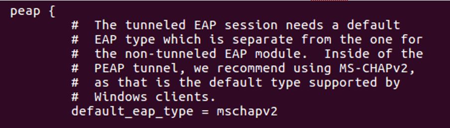
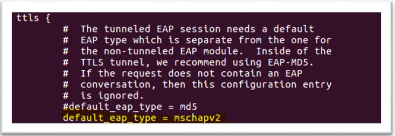
4. Configure mschap under /etc/freeradius/modules/mschap

802.1x_6
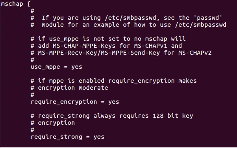
5. Start freeradius server. $sudo service freeradius restart. Make sure server is running and listening on port 1812

802.1x_7
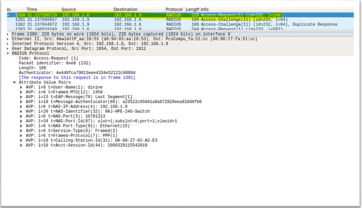
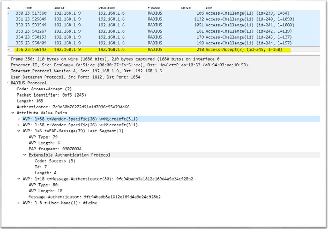
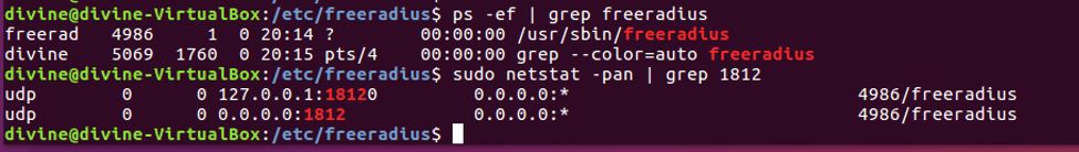
6. Now the server is running let’s test it to make sure it can handle incoming request. If you receive Access-Accept it means configuration is good. Try this command,

radtest <user> <password> <radius server ip> <port#> <shared secret>

802.1x_8

Setup Authenticator (switch)

I am using a HP 1920 series switch as an Authenticator. Setting authenticator is easy, all you need to do is configure Authentication server (RADIUS) IP address and shared secret key this is the same key we setup on Authentication server.

  1. Configure Authentication Method

802.1x_9

2. Configure Authentication Server IP, Shared secret key. Note: Shared secret key is same as we configured on Authentication server

802.1x_10

3. Associate RADIUS configuration with authentication and authorization

802.1x_11

802.1x_12

Generate self-signed certificate on Radius server and Client machine

We need SSL certificate on client and server depending which EAP method we use. Follow below steps to generate self signed certificate on client and server.

Generate CA (Certification Authority) certificate, server certificate and server key under /etc/freeradius/certs

divine@divine-VirtualBox:~/certs$ sudo openssl genrsa -des3 -out ca.key 1024
divine@divine-VirtualBox:~/certs$ openssl req -new -key ca.key -out ca.csr
divine@divine-VirtualBox:~/certs$ sudo openssl x509 -days 1095  -signkey ca.key -in ca.csr -req -out ca.crt

##Generate server key and certificate
divine@divine-VirtualBox:~/certs$ sudo openssl genrsa -des3 -out server.key 1024

##The signing request for the server certificate is generated by
divine@divine-VirtualBox:~/certs$ sudo openssl req  -new -key server.key -out server.csr

##A certificate serial number will be maintained in ca.serial
$echo -ne '01' > ca.serial

## Generate server certificate
divine@divine-VirtualBox:~/certs$ sudo openssl x509 -days 730 -CA ca.crt -CAkey ca.key  -in server.csr -req -out server.crt -CAserial ca.serial

Generate client key and certificate

We will sign client certificate with same CA which was used to sign server certificate so import CA certificate (ca.pem) and key (ca.key) from server to client machine

#Generate client private key
divine@divine-VirtualBox:~/certs$ sudo openssl genrsa -des3 -out client.key 1024

##The signing request for the client certificate is generated by
divine@divine-VirtualBox:~/certs$ sudo openssl req  -new -key client.key -out client.csr

##A certificate serial number will be maintained in ca.serial
$echo -ne '01' > ca.serial

## Generate client certificate
divine@divine-VirtualBox:~/certs$ sudo openssl x509 -days 730 -CA ca.pem -CAkey ca.key  -in client.csr -req -out client.crt -CAserial ca.serial

Procedure

Our setup is ready let’s try 802.1x authentication from Supplicant or client. I am using an Ubuntu 16.04 Virtual Machine as Supplicant. Enable 802.1x on Ubuntu, on the desktop click on System Settings -> Network -> Options

EAP-Type: PEAP with no server certificate validation

  1. In this mode certificate on server side is not needed, as you can see ‘No CA certificate is required’ checked in. In this mode no certificate exchanged between Authentication server and Supplicant

802.1x_13

2. Once 802.1x starts Supplicant will ask for user name password in my case it is divine/divine123. 802.1x_14

3. Supplicant gets IP address from DHCP which mean port on switch is now open. Try ping test to authenticator and server make sure ping test pass802.1x_15

EAP-Type: PEAP with server certificate validation

1.Update eap.conf file in Authentication server. Make below three changes .

private_key_file = ${conf_dir}/server.key
certificate_file = ${conf_dir}/server.crt
CA_file = ${conf_dir}/ca.crt

2. Import ca.pem file from Authentication server to Supplicant machine. Under CA certificate add ca.pem and uncheck ‘No CA certificate is required’. This will make sure to validate server certificate

802.1x_16

3. Disable and enable LAN interface (sudo ifconfig enp0s3 down & sudo ifconfig enp0s3 up). Below wireshark capture show EAP message exchange between Authenticator and Supplicant

802.1x_17

4. Make sure Supplicant gets DHCP IP address. Ping Authenticator or server and make sure ping test pass

EAP-TYPE:TLS

In this mode both server and client need certificate.

1.Follow instructions to generate certificate on client machine

2. Change default_eap_type to tls in eap.conf file, leave other setting as it is

802.1x_18
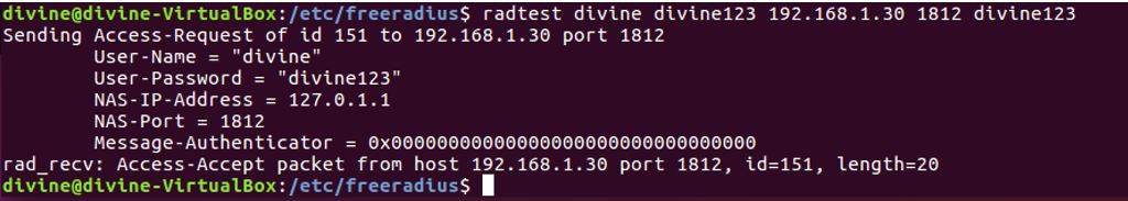
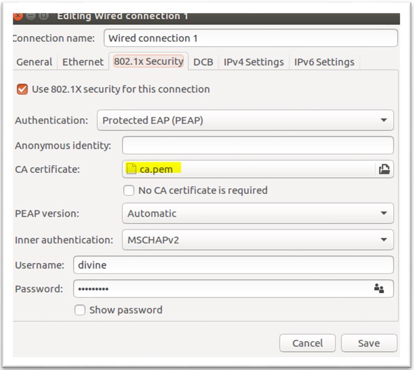
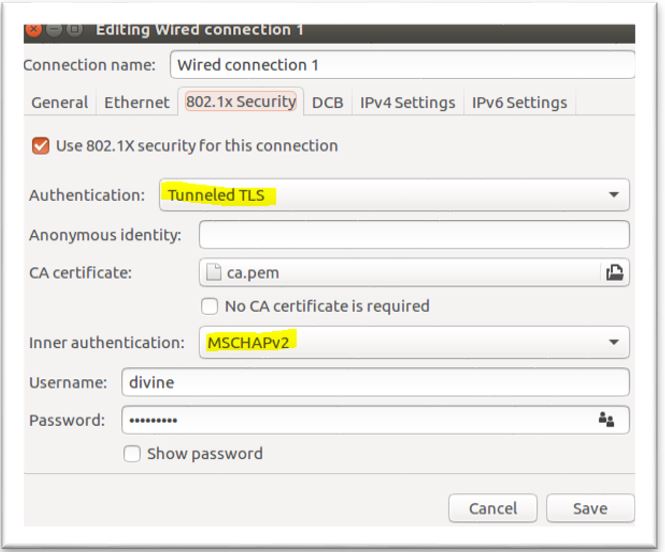
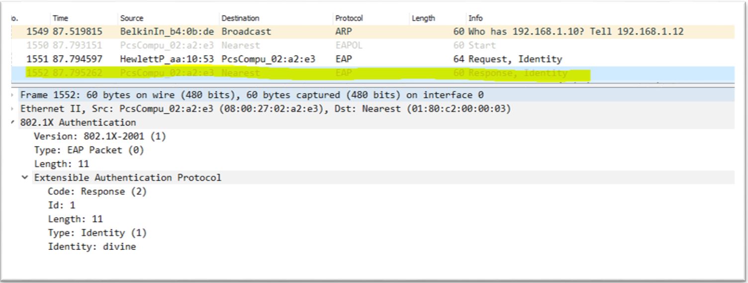
3. Configure Supplicant

802.1x_19

4. Disable and enable LAN port on supplicant to trigger 802.1x (sudo ifconfig enps03 down & sudo ifconfig enp0s3 up). Eap packets captured on Wireshark as you can see client and server side certificate exchanged

802.1x_20

5. Make sure Supplicant gets DHCP IP address. Ping Authenticator or server and make sure ping test pass

EAP-TYPE: TTLS (Tunneled TLS)

1.Change default_eap_type to ttls in eap.conf file also under ttls change default_eap_type to mschapv2. leave other setting as it is

802.1x_22

802.1x_23

2. Configure Supplicant. Tunneled tls doesn’t require certificate on supplicant

802.1x_31

3. Disable and enable LAN port on supplicant to trigger 802.1x (sudo ifconfig enps03 down & sudo ifconfig enp0s3 up). Eap packets captured on Wireshark as you can see client and server side certificate exchanged

802.1x_34

4. Make sure Supplicant gets DHCP IP address. Ping Authenticator or server and make sure ping test pass

Radius messages between Authenticator and Authentication server

1.Supplicant sends EAP-Start message to Authenticator. Destination mac used in this message is a multicast address:01:80:c2:00:00:03 and type:0x888e

802.1x_25

2. Authenticator ask for identify by sending Request-Identity message

802.1x_26

3. Supplicant respond to identity message by sending Response-Identity message. In this message Supplicant sends username (divine), destination mac is multicast

802.1x_27

4. Upon receiving the Response-Identity from Supplicant, Authenticator sends Radius message Access-Request to Authentication server. This message contains Authenticator ID, IP address and Supplicant username, mac address

802.1x_28

5. Authentication server look for username in user list if it finds username it sends challenge messages. Authentication servers sends multiple challenge messages to authenticate & authorize Supplicant

802.1x_29

6. After server satisfied with challenge response from Supplicate it sends Access-Accept. Upon receiving Access-Accept Authenticator sends Success EAP message to Supplicant and open the port

802.1x_30

Lab-46: MQTT protocol

1.0 Introduction

MQTT stands from Message Queue Telemetry Transport. MQTT is a publish/subscribe messaging transport protocol. It is a lightweight, open, simple, and designed so as to be easy to implement. These characteristics make it ideal for use in many situations, including constrained environments such as for communication in Machine to Machine (M2M) and Internet of Things (IoT) contexts where a small code footprint is required and/or network bandwidth is at a premium. The protocol runs over TCP/IP, or over other network protocols that provide ordered, lossless, bidirectional connections.

You can find MQTT standard here

2.0 How does MQTT work

MQTT is a relatively simple protocol, it works on publish and subscribe  paradigm. A client publishes topics to broker and broker forwards  message to all clients who subscribed for that topic. If no client subscribed to topic broker discards the message. A topic is a subject of interest for example a temperature sensor publishes temperature reading in a temperature topic.

A subscriber can subscribe to multiple topics and multiple subscribers can subscriber to a topic.

In the below picture we have a publisher client (Temp sensor) which publishes temperature topic to broker and two clients (Client-1 & Client-2) which subscribed to temperature topic. Broker simply pushes messages from temp sensor to client-1 & client-2. Broker job is to relay message from publisher client to subscriber client

mqtt_15

3.0 Key concepts of MQTT

These are the main concepts of MQTT

Broker: The broker accepts messages from clients and then delivers them to any interested clients. Messages belong to a topic. (Sometimes brokers are called “servers.”)

Broker or Server is a program or device that acts as an intermediary between Clients which publish Application Messages and Clients which have made Subscriptions. A Server:

– Accepts Network Connections from Clients.
– Accepts Application Messages published by Clients.

– Processes Subscribe and Unsubscribe requests from Clients.
– Forwards Application Messages that match Client Subscriptions

Client: A “device” that either publishes a message to a topic, subscribes to a topic, or both.

Client is a program or device that uses MQTT. A Client always establishes the Network Connection to the Server or broker. It can:

-Publish Application Messages that other Clients might be interested in.

– Subscribe to request Application Messages that it is interested in receiving.
– Unsubscribe to remove a request for Application Messages.
– Disconnect from the Server.

Topic: A namespace (or place) for messages on the broker. Clients subscribe and publish to a topic.

Publish: A client sending a message to the broker, using a topic name.

Subscribe: A client tells the broker which topics interest it. Once subscribed, the broker sends messages published to that topic. (In some configurations the broker sends “missed” messages.) A client can subscribe to multiple topics.

Unsubscribe: Tell the broker you are bored with this topic. In other words, the broker will stop sending messages on this topic.

4.0 QOS (Quality of service)

MQTT QOS is part of fixed header, bits 1 & 2. MQTT supports three types of quality of service QOS 0, QOS 1 and QOS 2.

QOS is implemented between sender and receiver. A sender can be a client which is publishing a topic or it can be a broker. A receiver can be a broker or client subscribed to a topic. So the end to end QOS between a publishing client and subscribing client can be broken down into two segments 1) between publishing client and broker and 2) between broker and subscribing client. Both segments are independent so segment 1 can be QOS 1 and segment 2 can be QOS 0.

mqtt_9

QOS 0: At most one delivery

QOS 0 is a best effort delivery. In this QOS receiver doesn’t acknowledge sender message. As soon as receiver receives message it delivers it onward. This QOS has lowest overhead

mqtt_10

mqtt_qos0

QOS 1: At least once delivery

This quality of service ensures that the message arrives at the receiver at least once. A QOS 1 PUBLISH Packet has a Packet Identifier in its variable header and is acknowledged by receiver using PUBACK message

If no acknowledgement received by sender it waits for certain time and then retransmit message with DUP flag =1. So in this QOS a subscribing client can receive duplicate message

mqtt_11

mqtt_qos1

QOS 2: Exactly once delivery

This is the highest quality of service, for use when neither loss nor duplication of messages are acceptable. There is an increased overhead associated with this quality of service.

This QOS guarantee that message received only once. It employs two step acknowledgement process and receiver doesn’t deliver message onwards until bidirectional acknowledgement completedmqtt_14

As can be seen from picture below only one message delivered to Client-1

mqtt_qos2

5.0 Wildcards

What if you need to subscribe to multiple topics it is not efficient to generate subscription message for each topic. MQTT support wildcards to subscribe multiple topics. There are two types of wildcards

  • Single level wildcard

The plus sign (‘+’ U+002B) is a wildcard character that matches only one topic level. For example, “sport/tennis/+” matches “sport/tennis/player1” and “sport/tennis/player2”, but not  “sport/tennis/player1/ranking”.

  • Multi-level wildcard

The hash sign (‘#’) is a wildcard character that matches multiple topic level. For example, “sport/#” matches “sport/tennis/player1” and “sport/tennis/player2

6.0 MQTT Packets

MQTT runs over TCP transport layer on port 1883. MQTT Control Packet consists of three parts, always in the following order as illustrated, 1) Fixed header 2) Variable header 3) Payload

mqtt_6

Fixed Header

Each MQTT Control Packet contains a fixed header. Fixed header is divided into MQTT control packet type and flags associated with control packet

mqtt_1

Control Packet type

Control Packet type represented by 4 bits in first byte. These are the MQTT Control Packet types

mqtt_2

mqtt_3

Flags

The remaining bits [3-0] of byte 1 in the fixed header contain flags specific to each MQTT Control Packet. As you can see QoS is applicable to PUBLISH packets only

mqtt_4

mqtt_5

Remaining Length

The Remaining Length is the number of bytes remaining within the current packet, including data in the variable header and the payload

Variable Header

Some types of MQTT Control Packets contain a variable header component. It resides between the fixed header and the payload. The content of the variable header varies depending on the Packet type. Packet Identifier field of variable header is common in several packet types

Variable header contains packet identifier

mqtt_7

The variable header component of many of the Control Packet types includes a 2 byte Packet Identifier field. These Control Packets are PUBLISH (where QoS > 0), PUBACK, PUBREC, PUBREL, PUBCOMP, SUBSCRIBE, SUBACK, UNSUBSCRIBE, UNSUBACK

Payload

Some MQTT Control Packets contain a payload as the final part of the packet. In the case of the PUBLISH packet this is the Application Message.

Control Packets that require a Payload

mqtt_8

7.0 RETAIN and Last Will

RETAIN and Last Will are important concept in MQTT. Let’s take a closer look at them

RETAIN

RETAIN flag is associated with PUBLISH packet. If the RETAIN flag is set to 1, in a PUBLISH Packet sent by a Client to a Server, the Server MUST store the Application Message and its QoS, so that it can be delivered to future subscribers whose subscriptions match its topic name. When a new subscription is established, the last retained message, if any, on each matching topic name MUST be sent to the subscriber. If the Server receives a QoS 0 message with the RETAIN flag set to 1 it MUST discard any message previously retained for that topic.

Suppose you have a client which publishes temp every 1/2 hr with RETAIN flag set to 0. If a subscriber subscribe to temp topic it needs to wait for next cycle when client publishes the temp. But if client publishes with RETAIN flag set to 1 then broker stores the last temp message and as soon as new subscriber subscribe to temp topic broker delivers the last stored message

mqtt_17

Last Will

Last Will in MQTT  is used to notify other clients about an ungraceful disconnect of a client. If a client disconnects abruptly then broker notifies to all clients by sending Last Will.

Last Will by a client is specified when client first sends CONNECT message to broker. Below is an example of CONNECT message with Last Will. In this example client set the Last Will topic ‘/plano/temp’ and Last Will message as ‘Temp sensor offline’. The reasoning behind this is when client abruptly disconnected may to due to battery dies or some hw failure broker will send the message ‘Temp sensor offline’ to all clients subscribed to topic ‘/plano/temp’. This info can be used to generate alert that a device went offline and need attention

If client disconnect gracefully using DISCONNECT message broker clears the Last Will

mqtt_18

Situations in which the Will Message is published include, but are not limited to:

  1. An I/O error or network failure detected by the Server.
  2. The Client fails to communicate within the Keep Alive time.
  3. The Client closes the Network Connection without first sending a DISCONNECT Packet.
  4. The Server closes the Network Connection because of a protocol error.


8.0 Keepalive

MQTT clients sends Control message to broker every Keepalive time interval. MQTT negotiate Keepalive time with broker in CONNECT message. Keepalive time measured in seconds.  If client doesn’t have Control message to send it can send PINGREQ message to broker just to keep the connection alive

If broker doesn’t receive any message from client for more than Keepalive interval it closes the network connect with client. If client doesn’t receive response to PINGREQ for more than reasonable time it closes connection with Server

A Keep Alive value of zero (0) has the effect of turning off the keep alive mechanism. This means that, in this case, the Server is not required to disconnect the Client on the grounds of inactivity

Below CONNECT message has Keepalive of 60 secs

mqtt_20

9.0 Demo of MQTT in Ubuntu

Let’s try out MQTT client & broker in Linux . I have Ubuntu 16.04 VM running in Virtual box

  • Install mosquitto broker and client

$sudo apt-get install mosquitto mosquitto-clients

  • Open two terminal windows. On one terminal publish topics for temperature and humidity

$mosquitto_pub -h localhost -t /plano/temperature -m “100 degree Celsius” $mosquitto_pub -h localhost -t /plano/humidity -m “50 percent”

  • On second terminal subscriber to topics. temperature and humidity reading displayed on terminal
$mosquitto_sub -h localhost -t /plano/#

There are many brokers available in public domain. Instead of local broker you can try iot.eclipse.org broker, replace localhost with iot.eclipse.org in above example

Example of RETAIN

Publish using RETAIN flag set -r.

$mosquitto_pub -h localhost -r -t /plano/temp -m "100 degree celsius"

Subscribe to topic /plano/temp and you will get the message retain by broker

$mosquitto_sub -h localhost -t /plano/temp

Example of Last Will

On first terminal run below command. This command will subscribe to topic /plano/temp  with Last Will

$mosquitto_sub -h localhost -t /plano/temp --will-topic /plano/temp --will-qos 1 --will-payload "Plano Temp sensor is offline" --will-retain

On second terminal run below command

$mosquitto_sub -h localhost -t /plano/temp

Now on first terminal enter ctrl+c to terminate program abruptly. A message ‘Plano Temp sensor is offline’ will be seen on second terminal

9.0 MQTT Python support

If you want to use MQTT programmatically then use paho MQTT library for Python. You can read more about Paho library here 

Install Paho Python library in Ubuntu 16.04

>pip install paho-mqtt

Paho is based on callback functions. Here is the summary of callback functions

mqtt_19

Below sample Python script to publish and subscribe. Code located here

https://github.com/sunnynetwork/mqtt

import paho.mqtt.client as mqtt
import time

# on_connect callback function called when CONNACK received from broker
def on_connect(client, userdata, flags, rc):
 print("Connected with result code"+ " " +str(rc))
 
# on_message callback function called when a PUBLISH message received from broker 
def on_message(client, userdata, message):
 print("'Received message ' "+ str(message.payload) + " ' on topic ' " + message.topic + "' with qos '" + str(message.qos))

#on_subscribe callback function called when SUBACK received from broker
def on_subscribe(client, userdata, mid, granted_qos):
 print("Subscribe_ack: " + str(mid) + " " + str(granted_qos))

# on_publish callback function called when PUBACK received from broker
def on_publish(client, userdata, mid):
 print("Publish_ack: " + str(mid))

broker_address = "iot.eclipse.org"
client = mqtt.Client("temp sensor")

# initialize callback functions
client.on_connect = on_connect
client.on_subscribe = on_subscribe
client.on_message = on_message
client.on_publish = on_publish

# connect with broker, default_port=1883, keepalive =60 sec 
client.connect(broker_address, 1883, 60)

# PUBLISH a topic to broker with qos=1, retain=True
client.publish("/plano/temperature/", "100 Degree Celsius", 1, True)
client.publish("/plano/humidity/", "70%", 1, True)
#print("Publish rc: " + str(rc))

# start loop
client.loop_start()
client.subscribe("/plano/#")
time.sleep(5)
client.loop_stop()

This is the result

Connected with result code 0
Publish_ack: 1
Publish_ack: 2
Subscribe_ack: 3 (0,)
'Received message ' 100 Degree Celsius ' on topic ' /plano/temperature/' with qos '0
'Received message ' 70% ' on topic ' /plano/humidity/' with qos '0


Resources

Beginners Guide To The MQTT Protocol

http://www.hivemq.com/mqtt-essentials/


Lab-39: Ansible for Network Automation

The goal of this lab is to learn Ansible basics and explore how it can help automate network device.

Ansible is a configuration management tool for servers. It is in the same line of tools as Chef, Puppet and Salt. The difference is, Ansible is agentless which mean it does not require any agent running on the server you are trying to configure. Which is a huge plus because network devices like switches and routers can’t be loaded with any agent

Ansible does it’s job by executing modules. Modules are python libraries. Ansible has a wide range of module . Click here  to lean about Ansible modules.

Ansible is basically made of these two components

  1. Modules: programs to perform a task
  2. Inventory file: This file contains remote server info like IP address, ssh connection info

When you install Ansible modules are loaded as part of installation. In my environment modules are located in this directory

/usr/lib/python2.7/site-packages/ansible/modules

To check what modules installed in your machine try this

$ansible-doc -l

To check the detail of a module try this

$ansible-doc -s $ansible-doc -s file

Prerequisite:

Install Ansible

$sudo pip install ansible

I am using Centos 7.3 for this lab. This is my Ansible version

$ansible --version
ansible 2.2.1.0
  config file = /etc/ansible/ansible.cfg
  configured module search path = Default w/o overrides

Topology:

I have two bare metal servers. Ansible is installed on one server (Ansible server) and another server (remote server) used for configuration

Procedure:

Setup passwordless ssh

Let’s setup  passwordless access to remote server so we don’t have to type password every time Ansible executed. Ansible prefer to login using ssh keys. To setup passwordless access try these commands on Ansible server and remote server.

In this example I am using username:virtuora and password:virtuora on remote server

1. Generate ssh-key on Ansible server as well as on remote server for a user.
$ssh-keygen -t rsa

2. Now copy remote server public ssh-key to Ansible server and Ansible server 
public key to remote server
$ssh-copy-id -i ~/.ssh/id_rsa.pub virtuora@192.254.211.168

3. Test it out by ssh to remote server from Ansible server and make sure 
ssh works passwordless
$ssh virtuora@192.254.211.168

Inventory File

Inventory file contains remote server reachability info (IP address, ssh user, port number etc). It is a simple text file with remote server IP address and optionally can contain ssh info. I named my inventory file ‘hosts’ . I have only one remote server (vnc-server) to configure

[vnc-server]
192.254.211.168 ansible_connection=ssh ansible_port=22 ansible_user=virtuora

If you have multiple remote servers you can group them like this

[db-servers]
192.254.211.166
192.254.211.167

[web-server]
192.254.211.165

There are two ways to execute Ansible

  1. Adhoc, which is Ansible command line
  2. Ansible playbook, which is essentially yaml with Jinja2 template

Ansible with adhoc

This is the simplest Ansible adhoc command. It is using localhost so inventory file is not needed

$ansible all -i "localhost," -c local -m shell -a 'echo hello world'
localhost | SUCCESS | rc=0 >>
hello world

Try below adhoc command with ping module. This is not a traditional ICMP ping. If successful it mean Ansible server can login to remote server and remote server has usable python configured

$ansible -i hosts -m ping vnc-server

-i: specify the inventory file, in this case  ‘hosts’

-m: Ansible module name, in this case ping

vnc-server: This is the remote server name in inventory file

$ansible -i hosts -m ping vnc-server
192.254.211.168 | SUCCESS => {
    "changed": false,
    "ping": "pong"
}

Now try same command with increase  verbosity -vvv flag, it will help us understand Ansible internal. If you study log you will find that Ansible first sftp the ping module from Ansible server to remote server, executes the module on remote server and then deletes it

Note: In a sense Ansible is not completely agent less. It requires remote server to support sftp and python to execute module, this could be a problem for network devices (switches & routers)  which doesn’t have these capabilities

$ansible -i hosts -m ping vnc-server -vvv
Using /etc/ansible/ansible.cfg as config file
Using module file /usr/lib/python2.7/site-packages/ansible/modules/core/system/ping.py
 ESTABLISH SSH CONNECTION FOR USER: virtuora
 SSH: EXEC ssh -C -o ControlMaster=auto -o ControlPersist=60s -o Port=22 -o KbdInteractiveAuthentication=no -o PreferredAuthentications=gssapi-with-mic,gssapi-keyex,hostbased,publickey -o PasswordAuthentication=no -o User=virtuora -o ConnectTimeout=10 -o ControlPath=/home/divine/.ansible/cp/ansible-ssh-%h-%p-%r 192.254.211.168 '/bin/sh -c '"'"'( umask 77 && mkdir -p "` echo ~/.ansible/tmp/ansible-tmp-1491254258.92-242743076706801 `" && echo ansible-tmp-1491254258.92-242743076706801="` echo ~/.ansible/tmp/ansible-tmp-1491254258.92-242743076706801 `" ) && sleep 0'"'"''
 PUT /tmp/tmpXP3MNY TO /home/virtuora/.ansible/tmp/ansible-tmp-1491254258.92-242743076706801/ping.py
 SSH: EXEC sftp -b - -C -o ControlMaster=auto -o ControlPersist=60s -o Port=22 -o KbdInteractiveAuthentication=no -o PreferredAuthentications=gssapi-with-mic,gssapi-keyex,hostbased,publickey -o PasswordAuthentication=no -o User=virtuora -o ConnectTimeout=10 -o ControlPath=/home/divine/.ansible/cp/ansible-ssh-%h-%p-%r '[192.254.211.168]'
 ESTABLISH SSH CONNECTION FOR USER: virtuora
 SSH: EXEC ssh -C -o ControlMaster=auto -o ControlPersist=60s -o Port=22 -o KbdInteractiveAuthentication=no -o PreferredAuthentications=gssapi-with-mic,gssapi-keyex,hostbased,publickey -o PasswordAuthentication=no -o User=virtuora -o ConnectTimeout=10 -o ControlPath=/home/divine/.ansible/cp/ansible-ssh-%h-%p-%r 192.254.211.168 '/bin/sh -c '"'"'chmod u+x /home/virtuora/.ansible/tmp/ansible-tmp-1491254258.92-242743076706801/ /home/virtuora/.ansible/tmp/ansible-tmp-1491254258.92-242743076706801/ping.py && sleep 0'"'"''
 ESTABLISH SSH CONNECTION FOR USER: virtuora
 SSH: EXEC ssh -C -o ControlMaster=auto -o ControlPersist=60s -o Port=22 -o KbdInteractiveAuthentication=no -o PreferredAuthentications=gssapi-with-mic,gssapi-keyex,hostbased,publickey -o PasswordAuthentication=no -o User=virtuora -o ConnectTimeout=10 -o ControlPath=/home/divine/.ansible/cp/ansible-ssh-%h-%p-%r -tt 192.254.211.168 '/bin/sh -c '"'"'/usr/bin/python /home/virtuora/.ansible/tmp/ansible-tmp-1491254258.92-242743076706801/ping.py; rm -rf "/home/virtuora/.ansible/tmp/ansible-tmp-1491254258.92-242743076706801/" > /dev/null 2>&1 && sleep 0'"'"''
192.254.211.168 | SUCCESS => {
    "changed": false,
    "invocation": {
        "module_args": {
            "data": null
        },
        "module_name": "ping"
    },
    "ping": "pong"
}

There are some variations to adhoc command, say if you want to specify user on command line instead of adding in inventory file (as I did)  you can try this

In this case I specify user using -u option

$ansible -i hosts -m ping vnc-server -u virtuora
167.254.211.168 | SUCCESS => {
    "changed": false,
    "ping": "pong"

Privilege Escalation

Privilege escalation allows to become another user that we login with. It can be  useful when we need to become sudo for some commands.

Say if you want to install a package on remote server which require sudo access. You can run it this way:

$ansible -i hosts -m yum -a “name=bridge-utils state=present” vnc-server –become -K

–become: privilege escalation is true

-K: ask password for SUDO

$ansible -i hosts -m yum -a "name=bridge-utils state=present" vnc-server --become -K
SUDO password:
167.254.211.168 | SUCCESS => {
    "changed": false,
    "msg": "",
    "rc": 0,
    "results": [
        "bridge-utils-1.5-9.el7.x86_64 providing bridge-utils is already installed"
    ]
}

Ansible Playbook

Running Ansible on command line is not very efficient, playbook allows you to run multiple tasks at once. You can share playbook with other users . A playbook contains multiple tasks. Playbook is written in yaml format with jinja2 template. To learn basics of playbook click here

This is a simple playbook which installs git package on remote server using yum. In this playbook I am defining variable (vars) and privilege escalation using become:true and become_method:sudo

$ cat yum-playbook.yml
---
- hosts: vnc-server
  vars:
    package_name: git
  tasks:
   - name: Install git package
     yum:
      state: present
      name: "{{ package_name }}"
     become: true
     become_method: sudo

hosts: remote server name on inventory file
vars: variable definition
become: privilege escalation
become_method: privilege escalation method

Execute playbook with -K to prompt for sudo password

$ansible-playbook -i hosts yum-playbook.yml -K
SUDO password:

PLAY [vnc-server] **************************************************************

TASK [setup] *******************************************************************
ok: [192.254.211.168]

TASK [Install git package] *****************************************************
changed: [192.254.211.168]

PLAY RECAP *********************************************************************
192.254.211.168            : ok=2    changed=1    unreachable=0    failed=0

changed=1 mean one change applied to remote server, in this case git package installed

Run it again

$ansible-playbook -i hosts yum-playbook.yml -K
SUDO password:

PLAY [vnc-server] **************************************************************

TASK [setup] *******************************************************************
ok: [192.254.211.168]

TASK [Install git package] *****************************************************
ok: [192.254.211.168]

PLAY RECAP *********************************************************************
192.254.211.168            : ok=2    changed=0    unreachable=0    failed=0

This time change=0 because git package was already present so no action performed on remote server. This is Ansible idempotent behavior, which mean  it performs action only when needed.

Configure Network device using Ansible

Configuring servers and all is good but I am interested in configuring  network devices like switches, routers. I like to know what Ansible can do for these devices. In my case I have an optical network switch which doesn’t support python or sftp. It does support ssh.

As I mentioned earlier Ansible modules need sftp and python configured on remote server. Let’s see how to configure an optical switch using  these constraint.

Ansible has a module called ‘raw’, read more about it here. This is the only module I found which doesn’t require sftp and python on remote server. This module sends commands on open ssh connection it doesn’t copy module to remote server.

This is my playbook with raw module looks like. This playbook provisions ports in my optical switch.

This playbook has two tasks 1) configure ports 2) set fail when port configuration task fail

In this playbook I have defined a dictionary of shelf/slot/port, configure ports task iterate through this dictionary to configure ports. I am also using ‘register’ to register output of configure ports task, this will  be used in next task to set ‘failed’ field

gather_facts: false is important here so Ansible doesn’t try to gather facts from our network device as it does on server. This parameter is true by default.

---
- hosts: optical-switch
  remote_user: virtuora
  gather_facts: false
  vars:
      ports:
           P1:
              slot_no: 2
              port_no: 7
              port_type: 10GER
           P2:
              slot_no: 2
              port_no: 8
              port_type: 10GER
           P3:
              slot_no: 2
              port_no: 9
              port_type: 10GER

      shelf_no: 1
      subslot_no: 0
  tasks:
   - name: configure ports
     raw: |
       configure
       set eqpt shelf "{{ shelf_no }}" slot {{ item.value.slot_no }} subslot "{{ subslot_no }}" port {{ item.value.port_no }}  pluggableInterfaceType {{ item.value.port_type }} admin-status up
       commit
     register: port_config
     with_dict: "{{ ports }}"

   - name: Set fail when port configuration fail
     fail:
        msg: "Configure ports failed"
     when: item.stdout.find('error') != -1
     with_items: "{{ port_config.results }}"
     #debug: msg="{{ port_config }}"

Execute the playbook. I don’t have password less ssh to device so -k used to provide password during run time

$ ansible-playbook -i hosts playbook-s100.yml -k
SSH password:

PLAY [s100-1] ******************************************************************

TASK [configure ports] *********************************************************
changed: [192.254.210.33] => (item={'key': u'P2', 'value': {u'slot_no': 2, u'port_no': 8, u'port_type': u'10GER'}})
changed: [192.254.210.33] => (item={'key': u'P3', 'value': {u'slot_no': 2, u'port_no': 9, u'port_type': u'10GER'}})
changed: [192.254.210.33] => (item={'key': u'P1', 'value': {u'slot_no': 2, u'port_no': 7, u'port_type': u'10GER'}})

TASK [Set pass/fail] ***********************************************************
skipping: [192.254.210.33] => (item={u'changed': True, u'_ansible_no_log': False, u'stdout': u'Commit complete.\r\n', u'_ansible_item_result': True, u'item': {u'key': u'P2', u'value': {u'slot_no': 2, u'port_no': 8, u'port_type': u'10GER'}}, u'stderr': u'\nWelcome to the FUJITSU 1FINITY S100\nCopyright Fujitsu Limited.\n\nShared connection to 192.254.210.33 closed.\r\n', u'rc': 0, u'invocation': {u'module_name': u'raw', u'module_args': {u'_raw_params': u'configure\n set eqpt shelf "1" slot 2 subslot "0" port 8 pluggableInterfaceType 10GER admin-status up\n commit'}}, u'stdout_lines': [u'Commit complete.']})
skipping: [192.254.210.33] => (item={u'changed': True, u'_ansible_no_log': False, u'stdout': u'Commit complete.\r\n', u'_ansible_item_result': True, u'item': {u'key': u'P3', u'value': {u'slot_no': 2, u'port_no': 9, u'port_type': u'10GER'}}, u'stderr': u'Shared connection to 192.254.210.33 closed.\r\n', u'rc': 0, u'invocation': {u'module_name': u'raw', u'module_args': {u'_raw_params': u'configure\n set eqpt shelf "1" slot 2 subslot "0" port 9 pluggableInterfaceType 10GER admin-status up\n commit'}}, u'stdout_lines': [u'Commit complete.']})
skipping: [192.254.210.33] => (item={u'changed': True, u'_ansible_no_log': False, u'stdout': u'Commit complete.\r\n', u'_ansible_item_result': True, u'item': {u'key': u'P1', u'value': {u'slot_no': 2, u'port_no': 7, u'port_type': u'10GER'}}, u'stderr': u'Shared connection to 192.254.210.33 closed.\r\n', u'rc': 0, u'invocation': {u'module_name': u'raw', u'module_args': {u'_raw_params': u'configure\n set eqpt shelf "1" slot 2 subslot "0" port 7 pluggableInterfaceType 10GER admin-status up\n commit'}}, u'stdout_lines': [u'Commit complete.']})

PLAY RECAP *********************************************************************
192.254.210.33             : ok=1    changed=1    unreachable=0    failed=0

Playbook ran fine and configured three ports on optical switch.

Execute playbook again

$ ansible-playbook -i hosts playbook-s100.yml -k
SSH password:

PLAY [s100-1] ******************************************************************

TASK [configure ports] *********************************************************
changed: [192.254.210.33] => (item={'key': u'P2', 'value': {u'slot_no': 2, u'port_no': 8, u'port_type': u'10GER'}})
changed: [192.254.210.33] => (item={'key': u'P3', 'value': {u'slot_no': 2, u'port_no': 9, u'port_type': u'10GER'}})
changed: [192.254.210.33] => (item={'key': u'P1', 'value': {u'slot_no': 2, u'port_no': 7, u'port_type': u'10GER'}})

TASK [Set pass/fail] ***********************************************************
failed: [192.254.210.33] (item={u'changed': True, u'_ansible_no_log': False, u'stdout': u'Error: access denied\r\n[error][2017-04-10 17:04:47]\r\n', u'_ansible_item_result': True, u'item': {u'key': u'P2', u'value': {u'slot_no': 2, u'port_no': 8, u'port_type': u'10GER'}}, u'stderr': u'Shared connection to 192.254.210.33 closed.\r\n', u'rc': 0, u'invocation': {u'module_name': u'raw', u'module_args': {u'_raw_params': u'configure\n set eqpt shelf "1" slot 2 subslot "0" port 8 pluggableInterfaceType 10GER admin-status up\n commit'}}, u'stdout_lines': [u'Error: access denied', u'[error][2017-04-10 17:04:47]']}) => {"failed": true, "item": {"changed": true, "invocation": {"module_args": {"_raw_params": "configure\n set eqpt shelf \"1\" slot 2 subslot \"0\" port 8 pluggableInterfaceType 10GER admin-status up\n commit"}, "module_name": "raw"}, "item": {"key": "P2", "value": {"port_no": 8, "port_type": "10GER", "slot_no": 2}}, "rc": 0, "stderr": "Shared connection to 192.254.210.33 closed.\r\n", "stdout": "Error: access denied\r\n[error][2017-04-10 17:04:47]\r\n", "stdout_lines": ["Error: access denied", "[error][2017-04-10 17:04:47]"]}, "msg": "The command failed"}
failed: [192.254.210.33] (item={u'changed': True, u'_ansible_no_log': False, u'stdout': u'Error: access denied\r\n[error][2017-04-10 17:04:47]\r\n', u'_ansible_item_result': True, u'item': {u'key': u'P3', u'value': {u'slot_no': 2, u'port_no': 9, u'port_type': u'10GER'}}, u'stderr': u'Shared connection to 192.254.210.33 closed.\r\n', u'rc': 0, u'invocation': {u'module_name': u'raw', u'module_args': {u'_raw_params': u'configure\n set eqpt shelf "1" slot 2 subslot "0" port 9 pluggableInterfaceType 10GER admin-status up\n commit'}}, u'stdout_lines': [u'Error: access denied', u'[error][2017-04-10 17:04:47]']}) => {"failed": true, "item": {"changed": true, "invocation": {"module_args": {"_raw_params": "configure\n set eqpt shelf \"1\" slot 2 subslot \"0\" port 9 pluggableInterfaceType 10GER admin-status up\n commit"}, "module_name": "raw"}, "item": {"key": "P3", "value": {"port_no": 9, "port_type": "10GER", "slot_no": 2}}, "rc": 0, "stderr": "Shared connection to 192.254.210.33 closed.\r\n", "stdout": "Error: access denied\r\n[error][2017-04-10 17:04:47]\r\n", "stdout_lines": ["Error: access denied", "[error][2017-04-10 17:04:47]"]}, "msg": "The command failed"}
failed: [192.254.210.33] (item={u'changed': True, u'_ansible_no_log': False, u'stdout': u'Error: access denied\r\n[error][2017-04-10 17:04:48]\r\n', u'_ansible_item_result': True, u'item': {u'key': u'P1', u'value': {u'slot_no': 2, u'port_no': 7, u'port_type': u'10GER'}}, u'stderr': u'Shared connection to 192.254.210.33 closed.\r\n', u'rc': 0, u'invocation': {u'module_name': u'raw', u'module_args': {u'_raw_params': u'configure\n set eqpt shelf "1" slot 2 subslot "0" port 7 pluggableInterfaceType 10GER admin-status up\n commit'}}, u'stdout_lines': [u'Error: access denied', u'[error][2017-04-10 17:04:48]']}) => {"failed": true, "item": {"changed": true, "invocation": {"module_args": {"_raw_params": "configure\n set eqpt shelf \"1\" slot 2 subslot \"0\" port 7 pluggableInterfaceType 10GER admin-status up\n commit"}, "module_name": "raw"}, "item": {"key": "P1", "value": {"port_no": 7, "port_type": "10GER", "slot_no": 2}}, "rc": 0, "stderr": "Shared connection to 192.254.210.33 closed.\r\n", "stdout": "Error: access denied\r\n[error][2017-04-10 17:04:48]\r\n", "stdout_lines": ["Error: access denied", "[error][2017-04-10 17:04:48]"]}, "msg": "The command failed"}
        to retry, use: --limit @/home/divine/ansible/vnc_install/playbook-s100.retry

PLAY RECAP *********************************************************************
192.254.210.33             : ok=1    changed=1    unreachable=0    failed=1

As you can see failed=1 because port configuration denied due to existing provisionig

I didn’t find other Ansible modules which can help to configure my device. However if you are using Juniper or Cisco you are at luck they have written special Ansible modules for their devices

Ansible has support for many situations. Here is what I learned

What if  you need to prompt user before running playbook tasks and exit if confirmation fail

- hosts: vnc-server
  vars_prompt:
     name: "confir"
     prompt: "Are you sure you want to un-install VNC, answer with 'yes'"
     default: "no"
     private: no
  tasks:

   - name: Check Confirmation
     fail: msg="confirmation failed"
     when: confirm != "yes"

How about if you need to execute a task based on output of previous task. In this example I am checking the status of ‘vnc’ application and if it is not running then only start it in second task

- name: Check VNC status
  command: vnc status
  register: vnc_status

- name: start vnc if not already running
  shell: nohup vnc start
  when: item.find('DOWN')
  with_items: "{{ vnc_status.stdout }}"

If your application doesn’t have way to check status, you can check status using Linux ‘ps’ command. Write a simple shell command like this to check application status

  - name: check vnc status
    shell: if ps -ef | egrep 'karaf' | grep -v grep > /dev/null; then echo "vnc_running"; else echo "vnc_not_running"; fi
    register: vnc_status

  - name: start vnc if not already running
    shell: nohup vnc start
    when: vnc_status.stdout.find('vnc_not_running') == 0

Ansible gather facts from remote server. You can use these facts  in your playbook. In this example I am using ‘ansible_pkg_mgr’ which will be either yum or apt-get depending on your Linux version

 - name: Install git package
     yum:
      state: present
      name: git
     when: ansible_pkg_mgr == "yum"
     become: true
     become_method: sudo

You can check facts gathered by Ansibile by running this command

ansible -i hosts -m setup vnc-server